
Stamped part quick locating device

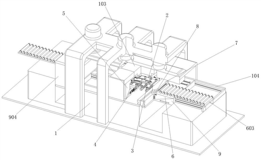
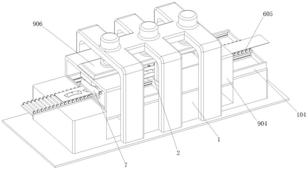
A technology of positioning device and stamping parts, applied in the field of steel back stamping production, can solve the problems of difficult quantitative conveying of steel plates, low material utilization rate, troublesome use, etc., and achieve the effects of convenient operation and use, accurate and timely positioning and fixing

Active Publication Date: 2020-09-08
安徽安路驰汽车部件有限公司
View PDF7 Cites 1 Cited by
  • Summary
  • Abstract
  • Description
  • Claims
  • Application Information

AI Technical Summary

Problems solved by technology

[0003] The applicant found that a whole steel plate needs to be used in the preliminary stamping process of the steel back, and the steel plate is transported between the stamping dies, and the horizontal stamping process is carried out on the steel plate. In order to improve the accuracy of the stamping process and the material utilization rate, The steel plate needs to be positioned during conveying and stamping, and the existing positioning structure generally uses lateral positioning pins to limit the left and right directions of the steel plate, but the steel plate needs to be fixed during stamping, and the steel plate needs to be moved during blanking and conveying. Different positioning structures need to be manually unlocked and locked, which is very cumbersome to use, and it is difficult to quantitatively transport steel plates, and manual feeding of raw materials is required, which requires high manual experience, resulting in low material utilization.

Method used


Image

  • Stamped part quick locating device
  • Stamped part quick locating device
  • Stamped part quick locating device

Examples


Embodiment Construction

[0036] In order to make the purpose, technical solutions and advantages of the present disclosure clearer, the present disclosure will be further described in detail below in conjunction with specific embodiments.

[0037] It should be noted that, unless otherwise defined, the technical terms or scientific terms used in one or more embodiments of the present specification shall have ordinary meanings understood by those skilled in the art to which the present disclosure belongs. "First", "second" and similar words used in one or more embodiments of the present specification do not indicate any order, quantity or importance, but are only used to distinguish different components. "Comprising" or "comprising" and similar words mean that the elements or items appearing before the word include the elements or items listed after the word and their equivalents, without excluding other elements or items. Words such as "connected" or "connected" are not limited to physical or mechanica...


PUM


Abstract

The one or more embodiments of the invention provides a stamped part quick locating device. The stamped part quick locating device comprises a fixed base. A lower die base is arranged in the middle position. An upper die base is arranged above the lower die base. A stamping sliding block is arranged above the upper die base. The left and right sides of the fixed base are symmetrically provided with transverse conveying racks. The inner sides of the transverse conveying racks are provided with transverse guide grooves. Vertical locating clamping rods of the stamped part quick locating device can be driven through trapezoidal clamping pressing blocks to synchronously and horizontally move to clamp raw materials to conduct locating. The trapezoidal clamping pressing blocks are pressed throughtrapezoidal hold-down pressing blocks synchronous with the stamping sliding block to do translational motion, so that stamping and fixing locating are synchronized. An upper clamping plate and a lower clamping plate of the stamped part quick locating device can do synchronous and horizontal movement with a progressive trapezoidal sliding block to quantitatively and progressively convey the raw materials. The progressive trapezoidal sliding block is driven through a lifting trapezoidal sliding block linked to the stamping sliding block to do translational motion, and then fixing locating and quantitative feeding operation of the raw materials can be completely synchronously.

Description

technical field [0001] One or more embodiments of this specification relate to the technical field of steel back stamping production, and in particular to a rapid positioning device for stamping parts. Background technique [0002] The purpose of the steel back is mainly to fix the friction material, which is easy to install on the brake system. The steel back is one of the components of the brake pad. At present, the disc brake is widely used in the market, and almost all disc brake pads The high-strength friction materials are all sintered on a steel plate, and move freely in the caliper under the push of the brake cylinder block, while the steel back is generally produced by stamping, and the steel back is generally designed with rivets and holes for convenience. It is installed on the caliper, and the steel plate material of the steel back is relatively thick, so the punching accuracy of the hole position is high during stamping production, and the raw material needs to ...

Claims


Application Information

Patent Timeline
Patent Type & Authority Applications(China)
IPC IPC(8): B21D22/02B21D43/00B21D43/08B21D45/08B21D53/88
CPCB21D22/02B21D43/003B21D43/08B21D45/08B21D53/88
Inventor 王雅名
Owner 安徽安路驰汽车部件有限公司
Learn More