a paint sprayer
A paint sprayer and fixer technology, applied in the direction of spraying device, etc., can solve the problems of affecting paint transportation, reducing the diameter of the pipeline, inconvenient movement, etc., and achieving the effect of avoiding the diameter of the pipeline becoming smaller, avoiding gaps, and preventing drying.
- Summary
- Abstract
- Description
- Claims
- Application Information
AI Technical Summary
Problems solved by technology
Method used
Image
Examples
Embodiment 1
[0025] like Figure 1-Figure 6 Shown:
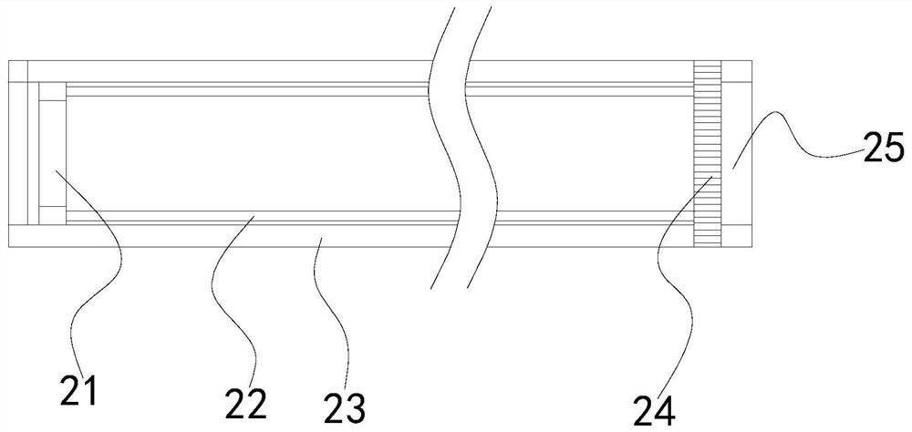
[0026] A paint sprayer according to the present invention, its structure includes a closing cover 1, a paint spraying pipeline 2, a fixer 3, a storage barrel 4, and a mobile vehicle 5, the closing cover 1 is installed on the upper end of the storage barrel 4, and the painting spraying pipeline 2 is embedded On the right side of the storage bucket 4, the upper end of the fixer 3 is in clearance fit with the right end of the paint spraying pipeline 2, and the lower end of the storage bucket 4 is attached to the top of the mobile vehicle 5, and the paint spraying pipeline 2 is formed by a scraping device 21. , a connecting rod 22, a spray pipe 23, a threaded block 24, and a spray port 25. The scraping device 21 is attached to the inside of the spray pipe 23, and the connecting rod 22 is located on the right side of the scraping device 21. The connection The rod 22 is welded on the left side of the threaded block 24, the injection port 25 a...
Embodiment 2
[0034] like Figure 7-Figure 8 Shown:
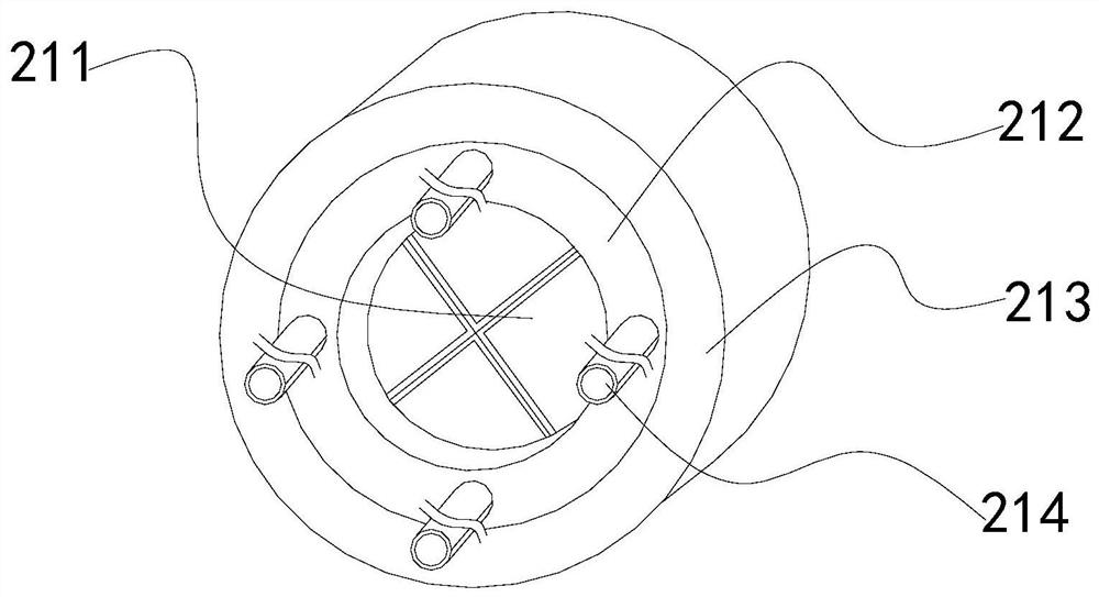
[0035]Wherein, the blocking mechanism 211 is provided with a blocking plate c1, a fixing groove c2, and a connecting ring c3. The connecting ring c3 is attached to the inside of the fixed ring 212. There are four blocking plates c1 in a right-angle fan-shaped structure, so that the paint can be sprayed better when used, and the four blocking plates c1 are spliced into a circle to avoid scraping The paint backs up where it was scraped off.
[0036] Wherein, the blocking plate c1 is provided with a magnet c11, a sector block c12, a rotating rod c13, and a limit block c14. side, the limiting block c14 is attached to the outer side of the fan-shaped block c12, the rotation rod c13 is connected with the limiting block c14, a limiting spring is provided inside the limiting block c14, and two magnets c11 are provided, With positive and negative magnetism respectively, the magnets c11 between the blocking plates c1 are attracted to each oth...
PUM
 Abstract
Description
Claims
Application Information
 - R&D Engineer
- R&D Manager
- IP Professional
- Industry Leading Data Capabilities
- Powerful AI technology
- Patent DNA Extraction
Browse by: Latest US Patents, China's latest patents, Technical Efficacy Thesaurus, Application Domain, Technology Topic, Popular Technical Reports.
© 2024 PatSnap. All rights reserved.Legal|Privacy policy|Modern Slavery Act Transparency Statement|Sitemap|About US| Contact US: help@patsnap.com


