
Dispenser and method for dispensing fluids

a technology of fluid dispenser and dispensing method, which is applied in the direction of carpet cleaner, packaging food items, packaged goods, etc., can solve the problems of uncontrollable dripping, restricted or even forgone cosmetic application, and still occurring dripping

Active Publication Date: 2012-10-23
LUCAS PUBLICATIONS
View PDF39 Cites 37 Cited by
  • Summary
  • Abstract
  • Description
  • Claims
  • Application Information

AI Technical Summary

Benefits of technology

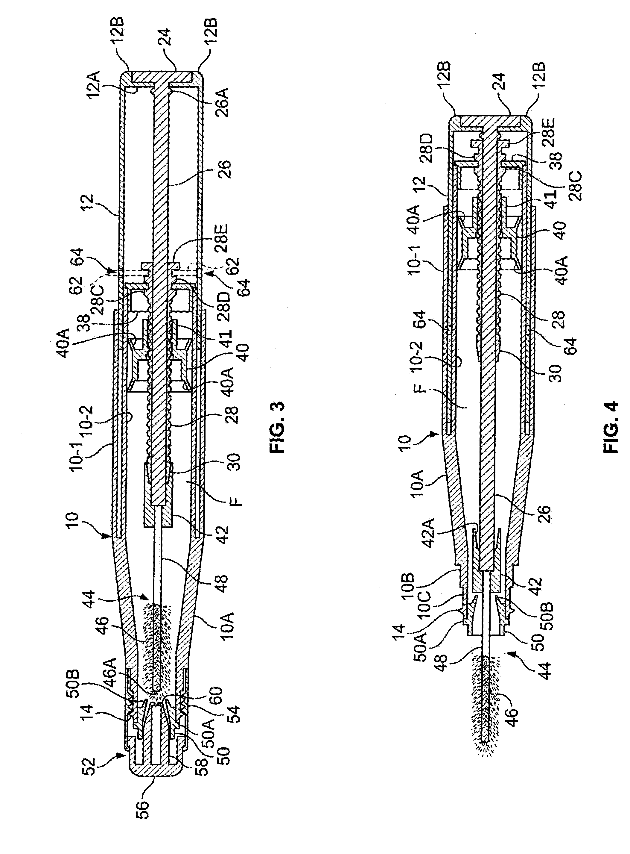
[0017]To prevent drying of the fluid when the dispenser is not in use, the disclosed embodiment has a number of sealing techniques. For example, to prevent leakage through the above-mentioned threaded sleeve, its inside end is tapered into a male fitting. The rod sliding through the threaded sleeve is fitted with a skirt that acts like a female fitting for engaging this male fitting much like a Luer fitting to prevent leakage through the threaded sleeve. This male and female fitting connect when the rod supporting the applicator brush is retracted into the case.

Problems solved by technology

However, there are many who choose to restrict or even forgo the application of cosmetics due to certain difficulties associated with application.
Often the brush contains excess fluid, causing uncontrollable dripping during application.
In many instances, dripping still occurs even when the brush is carefully scraped against the mouth of the bottle.
Users may tap or wipe off the excess, but this approach often creates a messy situation.
Also, a large amount of the product is then wasted.
Even if the user successfully removes the mascara tail and is fortunate to avoid dripping, often the brush is not evenly coated with mascara when it is extracted from the bottle.
This uneven distribution can prevent a neat and accurate application of the fluid, requiring multiple passes over the eyelashes.
As a result, some lashes receive too much fluid, while others do not receive any.
This tends to cause the eyelashes to clump together, creating an unsightly appearance which is difficult to rectify.
Further, a substantial portion of the product is often wasted due to being dried inside the container.
In some cases the mechanical design does not prevent air seepage so that the brush and cosmetic may dry inside the container.
Although the above example applies to mascara, many of the same disadvantages are also found with lip gloss, eyeliner, lip-liner, blush, nail polish and other liquid cosmetics.

Method used


Image

  • Dispenser and method for dispensing fluids
  • Dispenser and method for dispensing fluids
  • Dispenser and method for dispensing fluids

Examples


Embodiment Construction

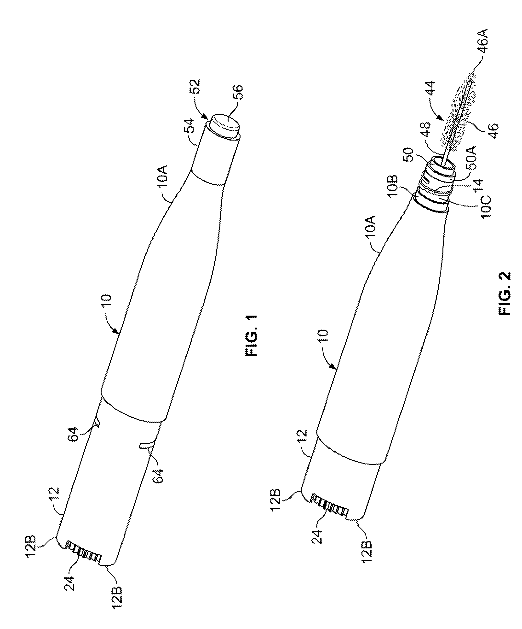
[0030]Referring to FIGS. 1-5, the illustrated fluid dispenser has a hollow base 12 telescopically fitted inside hollow case 10. For most of its length case 10 has the shape of a generalized right oval cylinder; that is, a tubular form with an oval cross-section. Case 10 tapers through front section 10A into a right cylindrical portion before stepping down into a smaller right cylindrical neck 10B. Projecting from neck 10B is a smaller cylindrical collar 10C with about 1½ turns of threads 14.

[0031]As shown in FIGS. 3 and 4, sections 10A, 10B and 10C have progressively thinner walls. The main portion of case 10 has a proximal double wall shown composed of outer wall 10-1 and inner wall 10-2. Inner wall 10-2 is shown extending beyond outer wall 10-1. Base 12 has the shape of a generalized right oval cylinder whose distal annular wall is sized to telescopically fit in the space between double walls 10-1 and 10-2. Having oval cross-sections, base 12 and case 10 cannot relatively rotate w...


PUM


Abstract

A fluid dispenser includes an applicator attached to a base, as well as a case that is at least partially filled with a fluid. The base and case are telescopically mounted together and can be relatively reciprocated to retract and extend the applicator relative to the case. A piston is mounted in the case for outwardly urging the fluid.

Description

CROSS-REFERENCES TO RELATED APPLICATIONS[0001]This application claims the benefit of U.S. Provisional Patent Application Ser. No. 60 / 947,130, filed 29 Jun., 2007, the contents of which are hereby incorporated by reference herein.BACKGROUND OF THE INVENTION[0002]1. Field of the Invention[0003]The present invention relates to fluid dispensing, and in particular, to devices and methods for storing and applying fluids.[0004]2. Description of Related Art[0005]Dispensers of fluids such as cosmetics are often sold in small bottles with an applicator brush extending from a cap.[0006]Cosmetics such as mascara, lip gloss and blush are widely used and enjoyed by many. People use cosmetics to enhance natural beauty and physical appearance. Often, confidence and self-esteem are elevated by results achieved when cosmetics are properly applied.[0007]However, there are many who choose to restrict or even forgo the application of cosmetics due to certain difficulties associated with application. For...

Claims


Application Information

Patent Timeline
Patent Type & Authority Patents(United States)
IPC IPC(8): B43K24/02
CPCA45D34/043A45D2200/055
Inventor FRANCAVILLA, FRANK
Owner LUCAS PUBLICATIONS
Learn More