
Signal transmission line, duplexer, multiplexer and communication equipment

A technology for signal transmission lines and signal lines, which is applied in the field of filters to achieve the effects of reducing the occupied space, being conducive to insertion loss, and having a high quality factor.

Active Publication Date: 2020-09-04
ROFS MICROSYST TIANJIN CO LTD
View PDF5 Cites 4 Cited by
  • Summary
  • Abstract
  • Description
  • Claims
  • Application Information

AI Technical Summary

Problems solved by technology

[0007] Although the above method achieves the purpose of improving the out-of-band suppression characteristics and isolation characteristics of the duplexer, the capacitor needs to be implemented by additionally setting interdigitated capacitors on the chip, which will inevitably lead to an increase in the size of the filter circuit, and includes this The problem of increasing the size of the high-frequency module of the filter circuit

Method used


Image

  • Signal transmission line, duplexer, multiplexer and communication equipment
  • Signal transmission line, duplexer, multiplexer and communication equipment
  • Signal transmission line, duplexer, multiplexer and communication equipment

Examples


no. 1 example

[0080] Figure 22 is a schematic diagram of a circuit architecture of a duplexer according to a fourth embodiment of the present invention. Such as Figure 22 As shown, in the duplexer 304, the first coupling unit LS1 is composed of a first inductance LS1a and a second inductance LS1b, wherein LS1b is the grounding inductance of a certain parallel branch of the receiving filter, and the first inductance LS1a and the second inductance The non-ground terminal of LS1b is connected, and the other terminal is suspended in the air. There is a parasitic capacitance C1 between the first inductor LS1a and the matching inductor at the signal output end of the receiving filter. There is electromagnetic coupling between the HZ-TL and the first coupling unit, forming a first coupling path (CP-R). The final effect is close to that of the first embodiment of the present invention.

[0081] Figure 23 is a schematic diagram of a circuit architecture of a duplexer according to a fifth embo...


PUM


Abstract

The invention discloses a signal transmission line, a duplexer, a multiplexer and communication equipment. The duplexer comprises an antenna, a transmitting filter, a receiving filter and an impedanceconverter, wherein the transmitting filter and the receiving filter are formed on the basis of acoustic resonators, and the impedance converter is the signal transmission line. The head end of a first metal signal line layer of the signal transmission line is connected with the antenna, and the tail end of the second metal signal line layer of the signal transmission line is connected with the antenna end of the receiving filter or the transmitting filter. According to the technical scheme, the signal transmission line has high characteristic impedance, impedance conversion is achieved in theduplexer design, meanwhile, the electrical length of the needed transmission line is shortened, the space occupied by the transmission line is reduced, and miniaturization design of devices is facilitated. In addition, an electromagnetic coupling path exists between the signal transmission line and a coupling unit in the receiving filter and / or the transmitting filter, and the out-of-band rejection characteristic and the isolation characteristic of the corresponding frequency band can be improved by adjusting the coupling mode and the coupling strength of the electromagnetic coupling path.

Description

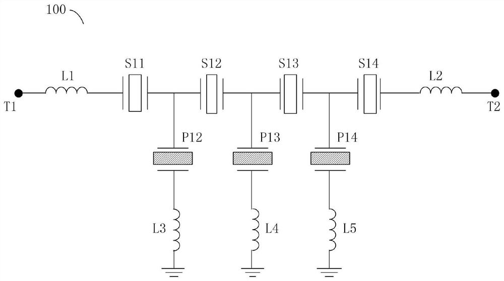
technical field [0001] The invention relates to the technical field of filters, in particular to a signal transmission line, a duplexer, a multiplexer and communication equipment. Background technique [0002] In recent years, the miniaturization and high-performance trend of communication equipment has accelerated, which poses higher challenges to the RF front-end. In the RF communication front end, on the one hand, miniaturization is achieved by reducing the size of the chip and package substrate, and on the other hand, better performance is achieved by reducing loss sources and better resonator matching design. In the existing filter structure, there are many passive components for matching, and at the same time, it is necessary to introduce more inductance, capacitance, coupling and other structures to improve specific performance such as roll-off insertion loss. [0003] A typical structure of an ordinary filter is as figure 1 as shown, figure 1 is a schematic diagra...

Claims


Application Information

Patent Timeline
Patent Type & Authority Applications(China)
IPC IPC(8): H03H7/01H01P1/213H03H7/38
CPCH01P1/213H03H7/0138H03H7/38
Inventor 边子鹏庞慰
Owner ROFS MICROSYST TIANJIN CO LTD
Learn More