Connecting structure of transformer tank cover and oil level indicator and transformer with connecting structure
A connection structure and oil level gauge technology, applied in the field of transformers, can solve the problems of increasing the processing steps of the box cover, inconvenient production, unfavorable sealing and use of transformers, etc., and achieve simplified processing steps, good interchangeability, deployment, installation and use, The effect of producing convenience
- Summary
- Abstract
- Description
- Claims
- Application Information
AI Technical Summary
Problems solved by technology
Method used
Image
Examples
Embodiment 1
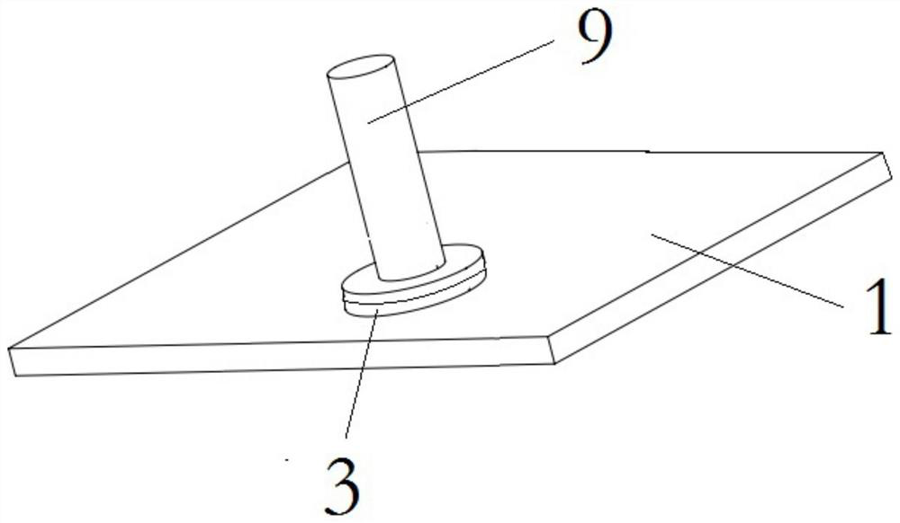
[0050] The transformer provided in this embodiment, such as figure 1 As shown, the transformer is a fully enclosed transformer, and at the same time, a threaded connection type oil level gauge 9 is installed on the fully enclosed transformer.
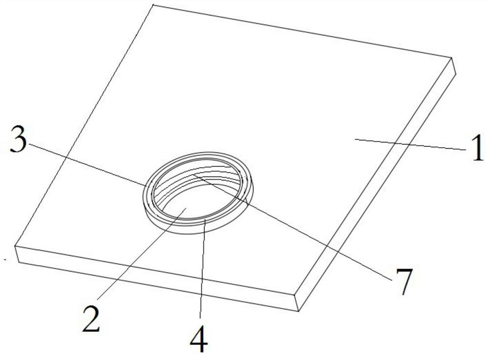
[0051] Such as figure 2 As shown, an installation hole 2 is provided on the case cover 1 of the transformer, and the diameter of the installation hole 2 is 60mm, and the first flange 3 is welded on the installation hole 2;
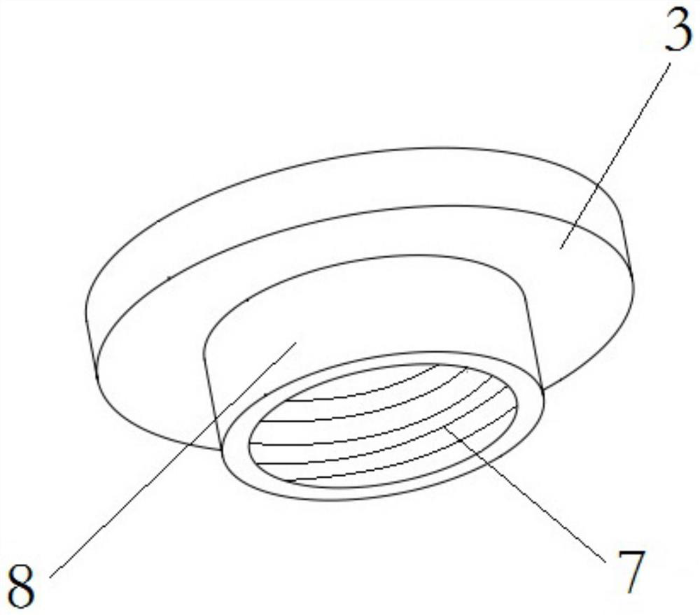
[0052] Such as image 3 As shown, specifically, the first flange 3 is a threaded flange, and an internal thread 7 is provided inside the first flange 3; one side of the first flange 3 has a first positioning flange 8, and the first flange 3 has a first positioning flange 8. The diameter of the first flange is 59mm; the first positioning flange 8 is inserted into the installation hole 2, the first flange 3 is limited, and then the edge of the first flange 3 is welded to the box cover 1 to realize the first The fi...
Embodiment 2
[0056] The transformer provided in this embodiment, such as Figure 4 As shown, the transformer is a fully enclosed transformer, and at the same time, a flange connection type oil level gauge 10 is installed on the fully enclosed transformer.
[0057] Such as Figure 5 As shown, a mounting hole 2 is provided on the case cover 1 of the transformer, and the diameter of the mounting hole 2 is 60mm, and a second flange 5 is welded on the mounting hole 2;
[0058] Such as Image 6 As shown, specifically, one side of the second flange 5 has a second positioning flange 6, and the diameter of the second flange is 59 mm; the second positioning flange 6 is inserted into the mounting hole 2, and the second flange 5 to limit the position, and then weld the edge of the second flange 5 to the box cover 1 to realize the fixing of the second flange 5 and the box cover 1; meanwhile, the edge of the second flange is also provided with several for fixed threaded holes;
[0059] The lower end...
Embodiment 3
[0062] The transformer provided in this embodiment, such as Figure 7 As shown, the transformer is a transformer with an oil conservator, and an oil conservator 11 is connected to the transformer with an oil conservator.
[0063] Such as Figure 5 As shown, a mounting hole 2 is provided on the case cover 1 of the transformer, and the diameter of the mounting hole 2 is 60mm, and a second flange 5 is welded on the mounting hole 2;
[0064] Such as Image 6 As shown, specifically, one side of the second flange 5 has a second positioning flange 6, and the diameter of the second flange is 59 mm; the second positioning flange 6 is inserted into the mounting hole 2, and the second flange 5 to limit the position, and then weld the edge of the second flange 5 to the box cover 1 to realize the fixing of the second flange 5 and the box cover 1; meanwhile, the edge of the second flange is also provided with several for fixed threaded holes;
[0065] The lower end of the connecting pip...
PUM
 Abstract
Description
Claims
Application Information
 - R&D
- Intellectual Property
- Life Sciences
- Materials
- Tech Scout
- Unparalleled Data Quality
- Higher Quality Content
- 60% Fewer Hallucinations
Browse by: Latest US Patents, China's latest patents, Technical Efficacy Thesaurus, Application Domain, Technology Topic, Popular Technical Reports.
© 2025 PatSnap. All rights reserved.Legal|Privacy policy|Modern Slavery Act Transparency Statement|Sitemap|About US| Contact US: help@patsnap.com


