
Low-altitude target detection method and system based on multi-source detector

A target detection and low-altitude target technology, which is applied in the direction of radio wave measurement systems, instruments, and measurement devices, can solve the problems of positioning and tracking accuracy that cannot meet the requirements, detect targets, and violate privacy rights, etc. Disruptive effect

Pending Publication Date: 2020-09-04
BEIJING INST OF ENVIRONMENTAL FEATURES
View PDF6 Cites 5 Cited by
  • Summary
  • Abstract
  • Description
  • Claims
  • Application Information

AI Technical Summary

Problems solved by technology

[0004] (2) There is a possibility of endangering public safety
[0005] (3) There is a problem of violation of privacy
So far, although many detection methods for low-altitude and small targets such as drones have emerged, they all have certain limitations:
[0007] 1. Targets equipped with radio jamming equipment cannot be detected by traditional radar detection methods;
[0008] 2. Positioning and tracking accuracy cannot meet the demand

Method used


Image

  • Low-altitude target detection method and system based on multi-source detector
  • Low-altitude target detection method and system based on multi-source detector
  • Low-altitude target detection method and system based on multi-source detector

Examples


Embodiment 1

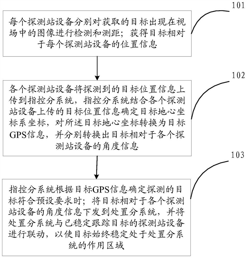
[0074] The key content of the low-altitude target detection and disposal based on multi-source detectors in this embodiment will be described in detail below by taking three detection devices as examples.

[0075] Calibrate the equipment of detection station S1, detection station S2 and detection station S3, and verify the detection, tracking and processing capabilities, operating range and information fusion capabilities of S1 equipment, S2 equipment and S3 equipment through cooperative small air targets (test drones).

[0076] Search and discover non-cooperative targets (target UAVs) through the visible light optical system and radar detection system. After finding the target, upload the target position information to the central control subsystem, track and exchange target information in real time (geocentric system coordinates T(x t ,y t ,z t )) to fuse the target trajectory (GPS information).

[0077] Compare the recorded information of the non-cooperative target (targe...

Embodiment 2

[0079] like figure 1 and figure 2 As shown, the multi-source detector positioning method of the embodiment of the present invention will be described below.

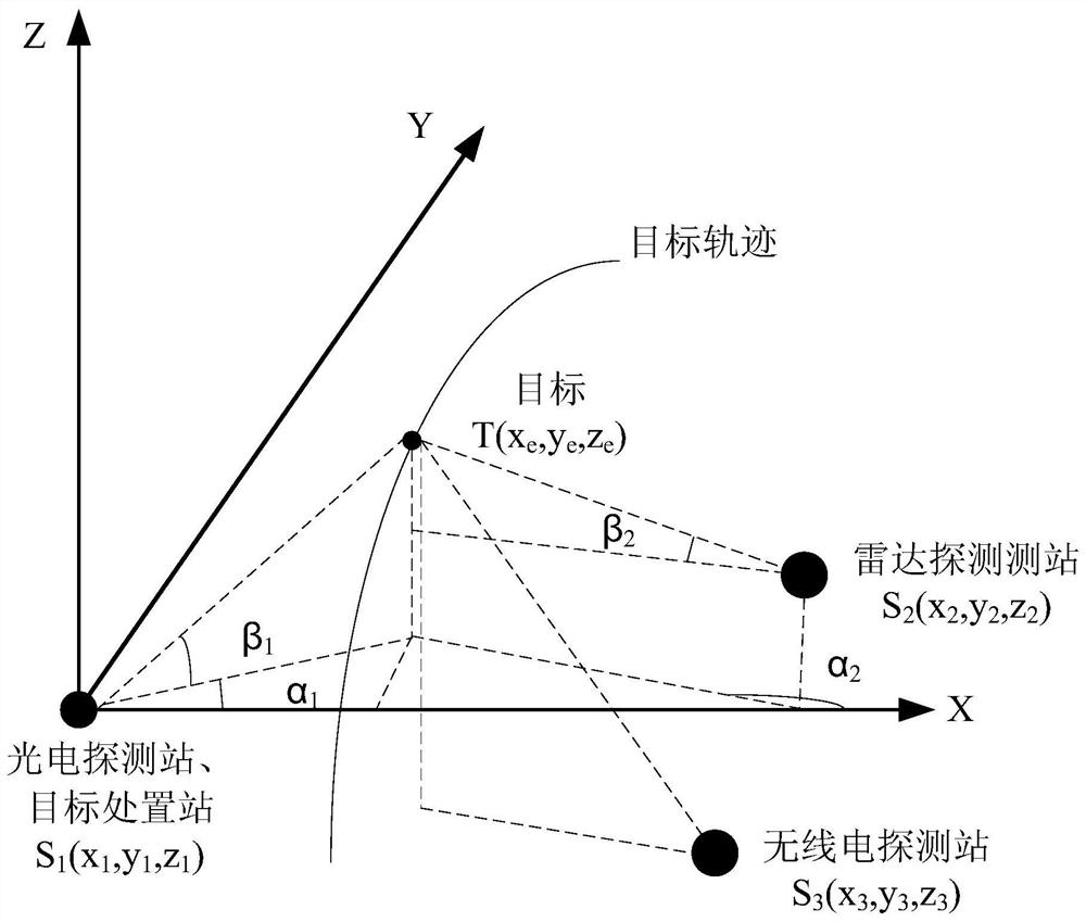
[0080] Select any two detection stations among the multi-source detection stations (taking the photoelectric detection station and the radar detection station as examples), and the coordinates are S 1 (x 1 ,y 1 ,z 1 ) and S 2 (x 2 ,y 2 ,z 2 ), the same target E(x e ,y e ,z e ) azimuth and elevation angles are α 1 、α 2 and beta 1 , β 2 .

[0081] like figure 2 The geometric relationship shown, the target E(x e ,y e ,z e ) is given by:

[0082]

[0083] Among them, tan is the tangent function, cot is the cotangent function, assuming that the position measurement and angle measurement of the photoelectric and radar detection station equipment are independent of each other, according to the measurement error theory, it can be deduced that (x e ,y e ,z e ) variance of positioning error usually us...

Embodiment 3

[0086] Embodiments of the present invention describe in detail the low-altitude target detection system based on multi-source detectors.

[0087] When the detection station equipment uses optical detectors, the optical detectors are used to collect the optical signals radiated, reflected and scattered by the scene within the field of view, and convert them into electrical image signals for output. Optical detectors may include infrared detectors and visible light detectors. Infrared detectors can be medium-wave or long-wave bands, with a 220mm diameter Cassegrain front stage; visible light detectors can use continuous zoom TV cameras. The optical detector is coaxial with the infrared detector. The photoelectric servo turntable mainly includes: horizontal dual-axis tracking frame (shaft system, torque motor, encoder, limit mechanism, etc.), servo controller. The tracking frame is a ground-level dual-axis tracking frame, which is composed of a vertical axis system, a horizontal ...


PUM


Abstract

The invention discloses a low-altitude target detection method and system based on a multi-source detector. The method comprises the steps that each detection station device detects and measures the distance of an obtained image of a target appearing in a view field; the position information of the target relative to each detection station device then is acquired; each detection station device uploads detected target position information to the command and control subsystem; the command and control subsystem determines a target geocentric coordinate system coordinate in combination with the target position information uploaded by each detection station device, converts the target geocentric coordinate into target GPS information, and converts the target GPS information into angle information of the target relative to each detection station device; the command and control subsystem determines that the detected target meets a preset requirement according to the target GPS information; and the angle information of the target relative to each detection station device is issued to a processing subsystem, and the processing subsystem is linked with the detection station device which stably tracks the target so that the target is enabled to be always stably located in the action area of the processing subsystem.

Description

technical field [0001] The invention relates to the technical field of target imaging detection, in particular to a gradient information-based low-light video image noise reduction processing method and system. Background technique [0002] In recent years, drones have been appearing in people's sights. In addition to being widely used in the military, UAVs are also rapidly expanding in the civilian market. Civilian drones are not only widely used in aerial photography, but also in fields such as agriculture, forestry and plant protection, security law enforcement, environmental protection research, mineral resource exploration, disaster emergency rescue, oil pipeline inspection, border defense, and maritime patrol. According to incomplete statistics, there are hundreds of thousands of consumer-grade drones in China at present, showing a doubling growth trend every year. The rapid popularity of drones is bringing unprecedented challenges to the security work of various coun...

Claims


Application Information

Patent Timeline
Patent Type & Authority Applications(China)
IPC IPC(8): G01S13/66G01S13/04G01V8/10
CPCG01S13/66G01S13/04G01V8/10
Inventor 宋志蛟黄建峰杨文佳李海涛殷亚国
Owner BEIJING INST OF ENVIRONMENTAL FEATURES
Learn More