
High-efficiency FBG high-temperature sensor and working and manufacturing method thereof

A high-temperature sensor and sensor technology, which is applied in the direction of instruments, thermometers, scientific instruments, etc., can solve the problems of excessive sensor function and size, low sensitivity, low reliability, etc., and achieve the elimination of wavelength nonlinear drift, high reflected light power, The effect of high temperature measurement accuracy

Pending Publication Date: 2020-09-04
XIANGTAN UNIV +1
View PDF0 Cites 0 Cited by
  • Summary
  • Abstract
  • Description
  • Claims
  • Application Information

AI Technical Summary

Problems solved by technology

[0007] At present, the existing FBG temperature sensor technology is relatively mature, but in the field of high temperature, it still has defects such as low sensitivity, low reliability, and low precision.
Especially in high-tech fields such as aerospace, traditional sensors have been unable to meet the needs of the industry due to non-functional deficiencies such as function and size, so it is urgent to develop a high-precision sensor

Method used


Image

  • High-efficiency FBG high-temperature sensor and working and manufacturing method thereof
  • High-efficiency FBG high-temperature sensor and working and manufacturing method thereof
  • High-efficiency FBG high-temperature sensor and working and manufacturing method thereof

Examples


Embodiment 1

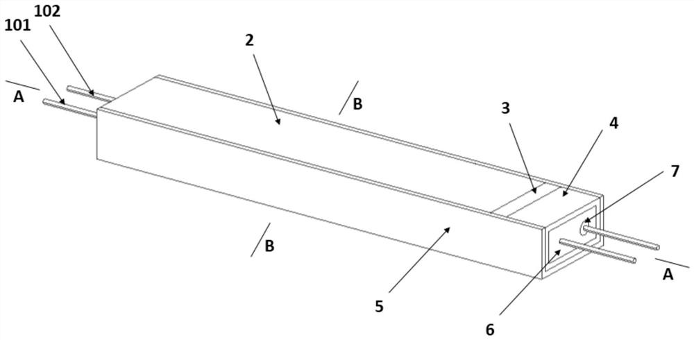
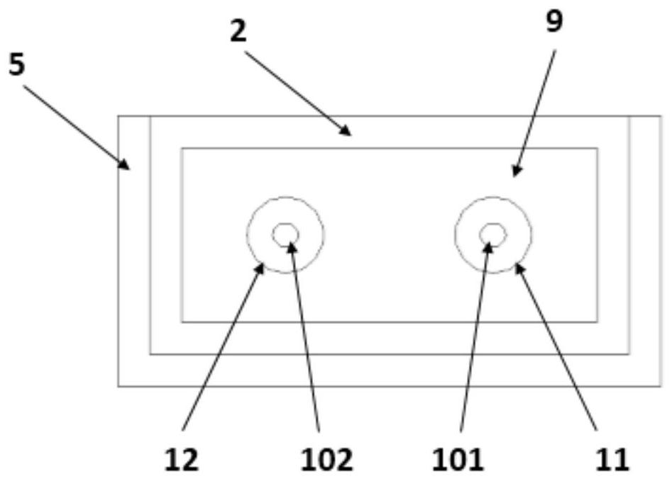
[0090] A high-efficiency FBG high-temperature sensor, the sensor includes a first sensitization FBG 101, a second sensitization FBG 102, a first package shell 2, a thermal bimetal 3, a second package shell 4, a guide rail base 5, and a third anchor Structure 6 , third thermal insulation sleeve 7 , second anchor structure 8 , thermal insulation area 9 , first anchor structure 10 , first thermal insulation sleeve 11 , and second thermal insulation sleeve 12 .

[0091] The optical fiber passes through the first thermal insulation sleeve 11 and the second thermal insulation sleeve 12, and the outer surface of the thermal insulation sleeve is filled with thermal insulation material, and the outer surface of the thermal insulation material is an encapsulation casing sleeve.

[0092] One end of the first sensitizing FBG101 is anchored by the first anchoring structure 10, and the other end is anchored by the third anchoring structure 6 after passing through the first insulation sleeve ...

Embodiment 2

[0094] A manufacturing method of a high-efficiency FBG high-temperature sensor includes fixing the FBG in a tube furnace, closing the tube furnace, inserting high-temperature cotton at both ends, and completing the annealing process.

Embodiment 3

[0096] Embodiment 2 is repeated, except that the thermal bimetal sheet is thermally deflected, thereby acting on the third anchoring structure 6, so that the temperature-measuring FBG in the first thermal insulation sleeve can recognize this force.


PUM

PropertyMeasurementUnit
Refractorinessaaaaaaaaaa
Densityaaaaaaaaaa
The average particle sizeaaaaaaaaaa

Abstract

The invention provides an efficient FBG (Fiber Bragg Grating) high-temperature sensor and a working and manufacturing method thereof. The sensor comprises an optical fiber which passes through the interior of the sensor in parallel and is provided with a first sensitization FBG for temperature measurement and a second sensitization FBG for temperature compensation along the axial direction of theoptical fiber, a heat preservation and insulation layer which can better protect a grid region and weaken the adverse effect of high temperature on a grating, and a thermal bimetallic strip which is amain temperature sensing power source component of the sensor. The efficient FBG high-temperature sensor can meet temperature monitoring under various high-temperature working conditions, is very small and exquisite, easy and convenient to manufacture and good in networking performance, and can establish a high-temperature monitoring network well. The efficient FBG high-temperature sensor can meet most high-temperature monitoring working conditions in the fields of energy exploitation, aerospace, civil engineering fire protection and the like, and has high reliability.

Description

technical field [0001] The invention relates to the field of high-temperature monitoring equipment, in particular to a high-efficiency FBG high-temperature sensor and its working and manufacturing methods. Background technique [0002] Optical fiber sensor is a sensor that converts the state of the measured object into a measurable optical signal. Since the birth of optical fiber sensor, it has been widely used in many traditional sensing fields because of its advantages of anti-electromagnetic interference, intrinsic safety, small size, light weight and easy embedding into materials. [0003] Harsh environments such as high temperature in deep space and strong electromagnetic interference will cause immeasurable damage to the aircraft during its service. Therefore, research on the reliability of aircraft in this harsh environment has become a key point. With the transformation of aerospace fuel, the working process of aircraft fuel tanks is in a high temperature state, an...

Claims


Application Information

Patent Timeline
IPC IPC(8): G01K11/32G01K11/3206
CPCG01K11/3206
Inventor 杨才千李帅杨国玉张立业唐人杰张旭辉许福
Owner XIANGTAN UNIV
Learn More