
Bridge deck structure of railway steel truss girder

A steel truss girder and railway technology, applied in bridges, bridge parts, bridge construction and other directions, can solve problems such as easy blockage of drainage pipes, and achieve the effects of improving connection stability, convenient operation and low cost

Inactive Publication Date: 2020-09-04
中铁二院重庆勘察设计研究院有限责任公司
View PDF7 Cites 0 Cited by
  • Summary
  • Abstract
  • Description
  • Claims
  • Application Information

AI Technical Summary

Problems solved by technology

[0005] The present invention intends to provide a bridge deck structure of railway steel truss girders to solve the problem in the prior art that the drains are drained and the drains are easily blocked

Method used


Image

  • Bridge deck structure of railway steel truss girder
  • Bridge deck structure of railway steel truss girder
  • Bridge deck structure of railway steel truss girder

Examples


Embodiment 1

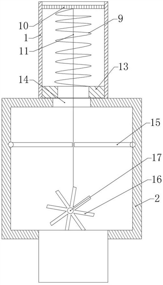
[0034] like figure 1 As shown, a bridge deck structure of a railway steel truss includes a bridge deck 3, a number of sleepers 4 are fixed on the bridge deck 3 (bolts can be used), and rails 5 are erected on the sleepers 4, and the rails 5 can be threaded spikes or The bolts are fixed on the sleeper 4. Several drainage pipes 1 are vertically installed on the bridge deck 3 , and both ends of the drainage pipes 1 penetrate through the bridge deck 3 . like figure 2 As shown, a drain 10 is provided at the water inlet of the drain pipe 1 , and a cleaning mechanism for cleaning the sundries on the drain 10 is installed on the drain pipe 1 .

[0035] like figure 2 As shown, the cleaning mechanism includes a rectangular power box 2, and the power box 2 is connected to the drain pipe 1. Specifically, the power box 2 is sealed and connected to the drain pipe 1, and the top and the top of the power box 2 are provided with through holes 14 and the drain pipe. Tube 1 is connected. A...

Embodiment 2

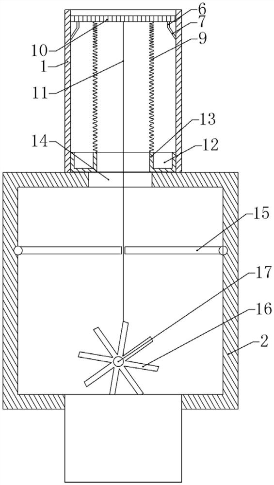
[0041] like image 3 As shown, the difference between this embodiment and the first embodiment is that a plurality of scrapers are glued to the bottom of the slip screen 10, and the scrapers are made of plastic. The scraper includes a vertical portion 6 connected to the drain screen 10 and an inclined portion 7 inclined to the outside of the drain screen 10 . The vertical portion 6 and the inclined portion 7 are integrally formed. The outer diameter of the support frame 13 is the same as the inner diameter of the drain pipe 1 . The support frame 13 is provided with an annular collecting groove 12 , the top of the collecting groove 12 is open, and the scraper can be accommodated in the collecting groove 12 .

[0042]In this embodiment, when the drain 10 is pulled down by the pull rope 11 , the scraper on the drain 10 can scrape off the dirt adhering to the inner wall of the drain pipe 1 , thereby realizing the cleaning of the drain pipe 1 . The scraped dirt can be dropped into...


PUM


Abstract

The invention relates to the technical field of bridges, and particularly relates to a bridge deck structure of a railway steel truss girder. The bridge deck structure comprises a bridge deck, whereina plurality of sleepers are arranged on the bridge deck, rails are erected on the sleepers, a plurality of drainage pipes are vertically arranged on the bridge deck, the two ends of each drainage pipe penetrate through the bridge deck, and a leakage net is arranged at a water inlet of each drainage pipe. The bridge deck structure further comprises a cleaning mechanism for pushing the leakage netsto move so as to throw out sundries on the leakage nets. The problem that drainage is conducted through a drainage pipe and the drainage pipe is easily blocked in the prior art can be solved.

Description

technical field [0001] The invention relates to the technical field of bridges, in particular to a bridge deck structure of a railway steel truss girder. Background technique [0002] Truss girder refers to a girder formed by connecting a web composed of many slats and two flanges. Steel truss girder bridge is a structural form in which a solid-web steel plate girder bridge is hollowed out according to certain rules. It is composed of brake connection system, bridge deck, support and bridge pier (abutment). [0003] Because steel has many advantages such as high strength, uniform material, good plasticity and toughness, and good weldability, steel is currently used to build bridges. Bridges built with steel have the advantages of large spanning capacity, suitability for industrial manufacturing (components can be prefabricated), easy transportation, fast installation, and easy repair and replacement of steel bridge components. [0004] However, because the steel is easy t...

Claims


Application Information

Patent Timeline
Patent Type & Authority Applications(China)
IPC IPC(8): E01D19/12E01D19/08
CPCE01D19/12E01D19/125E01D19/086
Inventor 赵品毅杜细春陈宇秦煜赖小刚苟彬彬陈星宇李中辉雷敏陈阳阳吕祥明谢茂宇
Owner 中铁二院重庆勘察设计研究院有限责任公司
Learn More