
Velocity limiter for an elevator

A technology of limiter and speed, used in elevators, transportation and packaging, etc., can solve the problems of service consumption, narrowness, problems, etc., and achieve the effect of reliable contact friction

Inactive Publication Date: 2011-09-21
INVENTIO AG
View PDF1 Cites 15 Cited by
  • Summary
  • Abstract
  • Description
  • Claims
  • Application Information

AI Technical Summary

Problems solved by technology

[0005] However, the described way of resetting the cable brake has proven to be disadvantageous in practice
It requires service outlays and is particularly problematic if there are narrow positional relationships due to structure and design
Many buildings require e.g. a small machine room above the lift shaft or even no machine room, which presents problems in ensuring the required accessibility for service personnel

Method used


Image

  • Velocity limiter for an elevator
  • Velocity limiter for an elevator
  • Velocity limiter for an elevator

Examples


Embodiment Construction

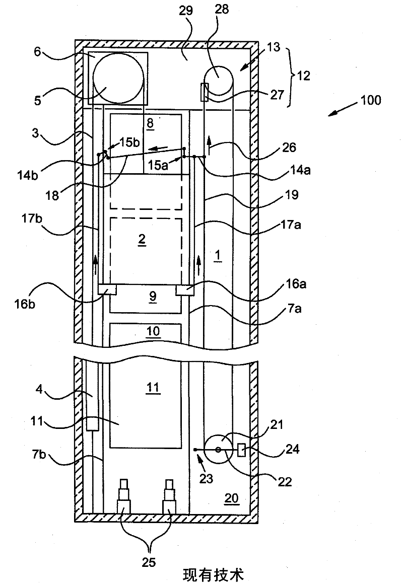
[0030] figure 1 An elevator installation 100 according to the prior art is shown schematically. It has an elevator car 2 that can be moved in an elevator shaft 1 and is connected to a counterweight 4 via a support device 3 . During operation, the carrier device 3 is driven by the drive wheels 5 of the drive unit 6 . The elevator car 2 and the counterweight 4 are guided by means of guide rails 7 a and 7 b extending at the height of the shaft.

[0031] The elevator installation 100 has the highest floor with the highest floor door 8 , the second highest floor with the second highest floor door 9 , other floors with other floor doors 10 and the lowest floor with the lowest floor door 11 . The shaft head 12 is accommodated in a machine room 29 in which the drive unit 6 and a speed limiter 13 are arranged which stop the elevator when the elevator car 2 overspeeds. For this purpose, a double lever 14 a and 14 b is respectively provided on two opposite sides of the elevator car 2...


PUM


Abstract

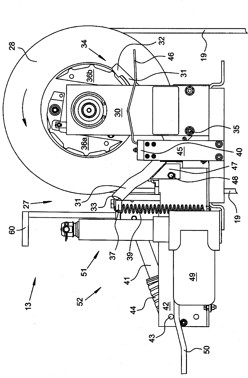
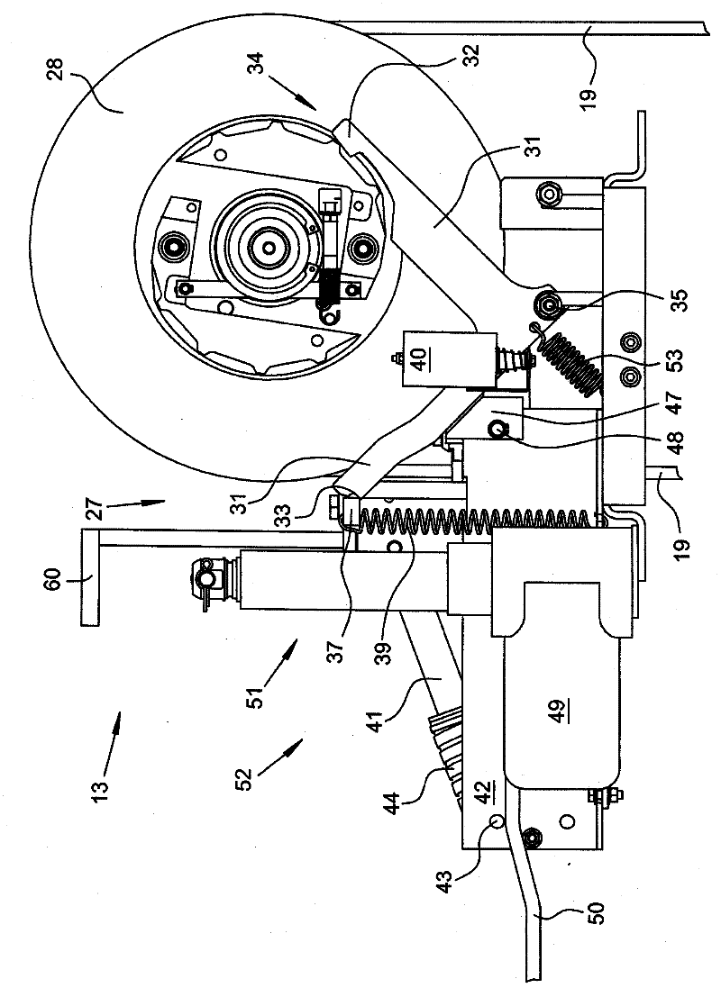
The present invention relates to a velocity limiter (13) in an elevator system (100), comprising a reset device (52) for a brake (27) of the velocity limiter (13), wherein the brake (27) can be automatically triggered and released mechanically, and remotely so. To this end, the velocity limiter (13) is equipped with a remotely-controllable triggering mechanism (34), for example a magnetic switch (40), and the reset device (52) is equipped with a remotely-controllable drive system (51), for example a lift system.

Description

technical field [0001] The invention relates to an elevator installation, which is guided by means of pulleys, in which an elevator car and a counterweight are driven by an electric motor in an elevator shaft. Background technique [0002] For safety reasons and also to comply with technical standards and legal regulations, such elevator installations are usually designed with a fall arrest device. The safety device is attached to the elevator car or the counterweight and brakes the movement of the elevator car or the counterweight and places the elevator car or the counterweight on, for example, the guide rails of the elevator car and / or the guide rails of the counterweight. The triggering of the safety device can be achieved, for example, by coupling the elevator car or the counterweight to the limiter cable by means of a linkage and lever mechanism. The limiter cables thus also describe the movement of the elevator car or the counterweight and are guided on the one hand ...

Claims


Application Information

Patent Timeline
Patent Type & Authority Applications(China)
IPC IPC(8): B66B5/04
CPCB66B5/044B66B1/26B66B1/32B66B5/04
Inventor 莱托·德莱雅罗尔夫·法尔尼
Owner INVENTIO AG
Learn More