Eureka AIR delivers breakthrough ideas for toughest innovation challenges, trusted by R&D personnel around the world.

High pressure powder feeder unit and application thereof

A powder feeder and high-pressure technology, applied in conveyors, conveying bulk materials, metal material coating processes, etc., can solve problems such as insufficient sealing effect, insufficient powder feeding accuracy, and equipment difficult to meet production process requirements, etc. To achieve the effect of good sealing effect, safe and reliable use, and economical and applicable overall structure

Pending Publication Date: 2020-09-04
株洲辉锐增材制造技术有限公司
View PDF1 Cites 2 Cited by
  • Summary
  • Abstract
  • Description
  • Claims
  • Application Information

AI Technical Summary

Problems solved by technology

This structure does not involve the powder plate structure, and the powder feeding is not accurate enough
[0007] Moreover, the sealing performance of the existing powder feeding unit is difficult to apply to high-pressure situations, and often the sealing effect cannot meet the needs of high-pressure equipment, and the equipment is difficult to meet the production process requirements
[0008] After searching, no high-pressure powder feeder unit with good airtightness suitable for spraying and laser cladding technology was found

Method used


Image

  • High pressure powder feeder unit and application thereof
  • High pressure powder feeder unit and application thereof
  • High pressure powder feeder unit and application thereof

Examples


Embodiment 1

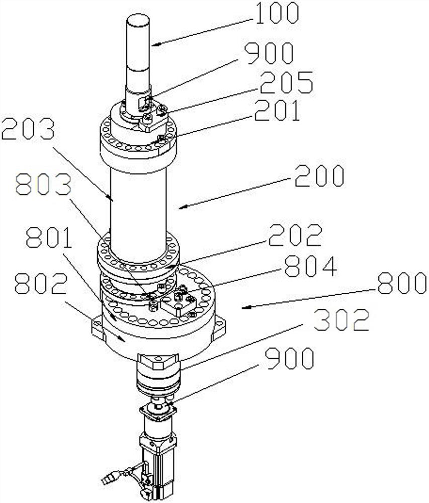
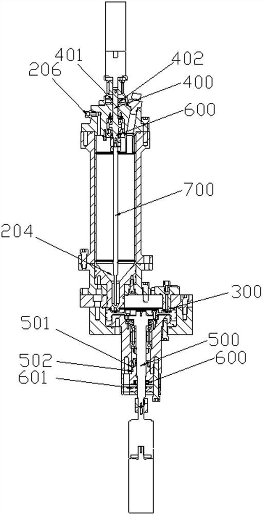
[0046] Such as Figure 1~Figure 6 As shown, the high-pressure powder feeder unit includes a drive unit 100, a powder storage unit 200 and a powder tray unit 300 arranged in sequence, and the output end of the drive unit 100 is connected with a drive shaft 400 extending into the powder storage unit 200. In this implementation The drive unit 100 in the example is a DC motor, one end of the drive shaft 400 is connected to the output end of the motor through a coupling 900, the other end of the coupling 900 is connected to a powder stirring rod 700, and the powder storage unit 200 includes a powder storage tank body 203 and an installation The upper end cap 201 and the lower end cap 202 at both ends of the powder storage tank body 203; the outer edge diameters of the upper and lower end caps are larger than the outer wall diameter of the powder storage tank body 203, and the structure of the powder storage tank body 203 is a cylinder with connecting ears , the connecting ear and t...


PUM


Abstract

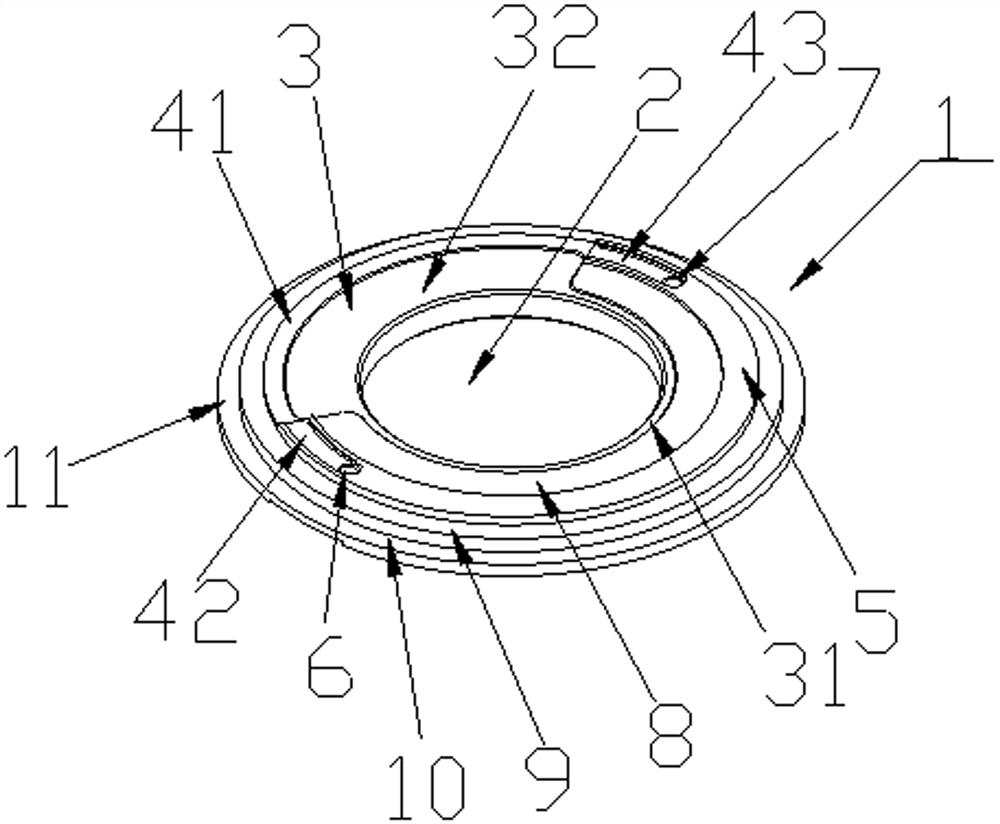
The invention relates to a high pressure powder feeder unit. The high pressure powder feeder unit comprises a driving unit, a powder storing unit and a powder disc unit arranged successively. An output end of the driving unit is connected to a driving shaft extending into the powder storing unit. The powder disc unit comprises an upper powder disc and a lower powder disc. The upper powder disc comprises a disc body, wherein an air inlet is formed in the center of the disc body, an air overflowing breadth is arranged along the outer edge of the air inlet, the lower powder disc is a cover body of a ring concave part structure and comprises a fixed protrusion arranged at the center, and a powder disc rotating shaft mounting hole is formed in the center of the fixed protrusion. The high pressure powder feeder unit combines the driving unit, the powder storing unit and the powder disc unit together. By improving the structures of the driving unit, the powder storing unit and the powder discunit, the whole powder feeding unit is extremely good in sealing property, is suitable for a high pressure condition and is enough to meet a production demand of production. The unit can be suitablefor being used in a condition not enough in pressure, can meet the demand of cold spraying, thermal spraying and laser cladding techniques, is wide in application and has a good market prospect.

Description

technical field [0001] The invention belongs to the technical field of laser surface modification, and in particular relates to a high-pressure powder feeder unit and its application. Background technique [0002] The function of the powder feeder is to accurately feed the powder into the laser melting pool or directly spray the powder onto the surface of the substrate through the spray gun according to the requirements of the processing technology, and ensure that the powder can be conveyed continuously, uniformly and stably during the processing. According to different types of process characteristics and powder types, the types of powder feeders that have been developed at home and abroad mainly include screw type powder feeder, rotary table type powder feeder, scraper type powder feeder, capillary type powder feeder, drum type powder feeder, etc. Powder feeder, electromagnetic vibration powder feeder and boiling powder feeder. [0003] In the production of cold spraying...

Claims


Application Information

Patent Timeline
IPC IPC(8): B65G53/06B65G53/36B65G53/34C23C24/10
CPCB65G53/06B65G53/34B65G53/36C23C24/10
Inventor 程畅栋欧益忠韩云杰黄艺思
Owner 株洲辉锐增材制造技术有限公司
Why Eureka
Eureka Blog
Learn More