
A ring pipe positioning and repairing method of complex structure of engine

A complex structure and engine technology, applied in metal processing equipment, auxiliary welding equipment, welding equipment, etc., can solve the problems of high positioning accuracy, poor consistency, and poor loop production consistency, so as to improve assembly positioning accuracy and improve production. Efficiency, the effect of shortening the assembly cycle

Active Publication Date: 2022-04-19
XIAN SPACE ENGINE CO LTD
View PDF6 Cites 0 Cited by
  • Summary
  • Abstract
  • Description
  • Claims
  • Application Information

AI Technical Summary

Problems solved by technology

[0004] Due to the complex structure and high dimensional accuracy, the ring pipe file repair, positioning and assembly process are difficult, which are mainly reflected in: 1) The space envelope size of the ring pipe components is large, and the positioning accuracy requirements are high, and the clearance requirements, angle requirements and parallelism requirements must be met. 2) When the titanium tube is sampled and repaired, the clamping positions and angle directions of the 18 pieces of tees and crosses on the ring tube are not fixed, which makes it difficult to guarantee the repair accuracy of the ring tube, and the production consistency of the ring tube is poor; 3) There are 37 branch conduits connected to the ring pipe. The poor consistency of the ring pipe production leads to the failure of mass production of the 37 branch conduits, which seriously restricts the engine assembly cycle

Method used


Image

  • A ring pipe positioning and repairing method of complex structure of engine
  • A ring pipe positioning and repairing method of complex structure of engine
  • A ring pipe positioning and repairing method of complex structure of engine

Examples


Embodiment Construction

[0021] The present invention will be further described below in conjunction with the accompanying drawings and embodiments, and the present invention includes but not limited to the following embodiments.

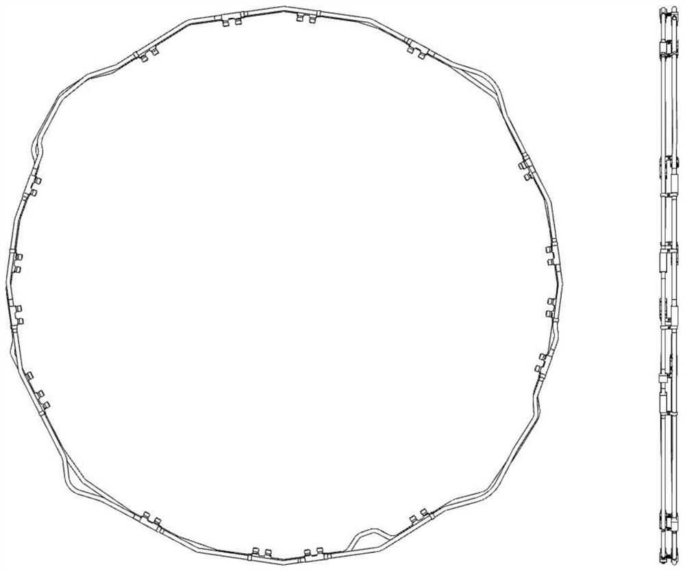
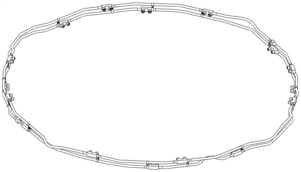
[0022] Examples of the present invention are figure 1 , figure 2 As shown, it is an engine ring pipe assembly, which is composed of two ring pipes arranged side by side, namely the oxidizer ring pipe and the fuel ring pipe, and the diameter of the pipe fittings is about 1.6m. The oxidant ring pipe is welded by 8 crosses, 1 tee and 8 titanium tubes, with a total of 17 welds. The fuel ring is welded by 8 crosses, 1 tee and 9 titanium tubes, with a total of 18 welds.

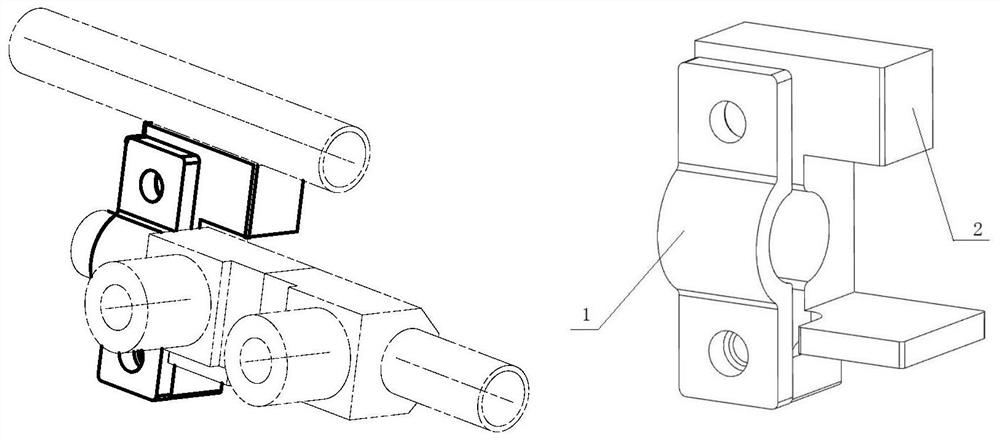
[0023] The present invention uses positioning clips to fix the tee and cross on the ring pipe; the positioning clips are two pieces that are fastened to each other, and the fastening places form a cylindrical through hole parallel to the plane where the ring pipe is located, and the inner diameter of the thro...


PUM


Abstract

The invention provides a method for positioning and repairing the ring pipe of the complex structure of the engine. The tee and the cross on the ring pipe are fixed by using positioning clips that are fastened to each other, and a cylindrical through hole parallel to the plane where the ring pipe is formed is formed at the fastening place; When a positioning clamp block fixes the tee and the ring pipe, or fixes the cross and the ring pipe, the ring pipe connected to one end of the tee or cross passes through the through hole, and the positioning clamp block is perpendicular to the radial sides of the through hole. At the axial end of the three-way or cross-way, the side of the positioning clamp parallel to the plane of the ring tube is pressed against the adjacent ring tube, or the side of the positioning clamp parallel to the plane of the ring tube has a protrusion in the direction of the axis of the ring tube , the L-shaped angle formed by the protrusion and the positioning clamp block is close to the adjacent ring pipe; after fixing the tees and crosses on the two ring pipes, repair each titanium pipe one by one. The invention can reduce the difficulty of positioning and repairing the annular pipe assembly with complex structure, shorten the production cycle, ensure the positioning accuracy, and improve the assembly consistency of the engine.

Description

technical field [0001] The invention relates to a positioning and repairing method, which belongs to the technical field of assembly and welding of pipeline connectors with complex structures. Background technique [0002] The main pipeline for conveying propellant on the attitude control engine is usually a ring pipe assembly welded by titanium alloy general parts and titanium pipes. The shape and structure of the pipeline of the ring pipe assembly is complex. After the ring pipe is assembled, the gap with the surrounding components is very small, and the assembly position accuracy of each channel is high. There is no compensation margin for the structure and span of the ring pipe. It is required that the ring pipe must be repaired and welded once to pass, otherwise the sawing repair will cause interference between the ring pipe and the cabin structure, and then it cannot be assembled. [0003] The main pipeline of a certain attitude control engine is two ring pipes arrang...

Claims


Application Information

Patent Timeline
Patent Type & Authority Patents(China)
IPC IPC(8): B23K37/053B23K37/04B23K37/00
CPCB23K37/053B23K37/0426B23K37/00
Inventor 杨华赵小青闫明辉张华龙刘涛蔡强顺杨永强
Owner XIAN SPACE ENGINE CO LTD
Learn More