


Quick Research
Generate reliable direction feasibility study reports for your R&D in just a few steps.

Technical Q&A
Discover and master advanced knowledge NOW. Basics, ideas, possibilities, all at once.

Find Solutions
As an expert in R&D theories, this can generate solutions to your technical problems instantly.

Evaluate Feasibility
Analyze your overall solution with one click, know your potential R&D risks in advance.

Monitor Landscape
Get weekly tech updates, stay abreast of the latest tech innovations and key insights.
A corner cutting machine for diode processing
An angle cutting machine and diode technology, applied in the direction of semiconductor devices, electrical components, circuits, etc., can solve the problems of wasting time, reducing the work efficiency of workers, increasing the labor intensity of workers, etc., and achieve the effect of improving work efficiency and avoiding collisions
- Summary
- Abstract
- Description
- Claims
- Application Information
AI Technical Summary
Problems solved by technology
Method used
Image

Examples
Embodiment 1
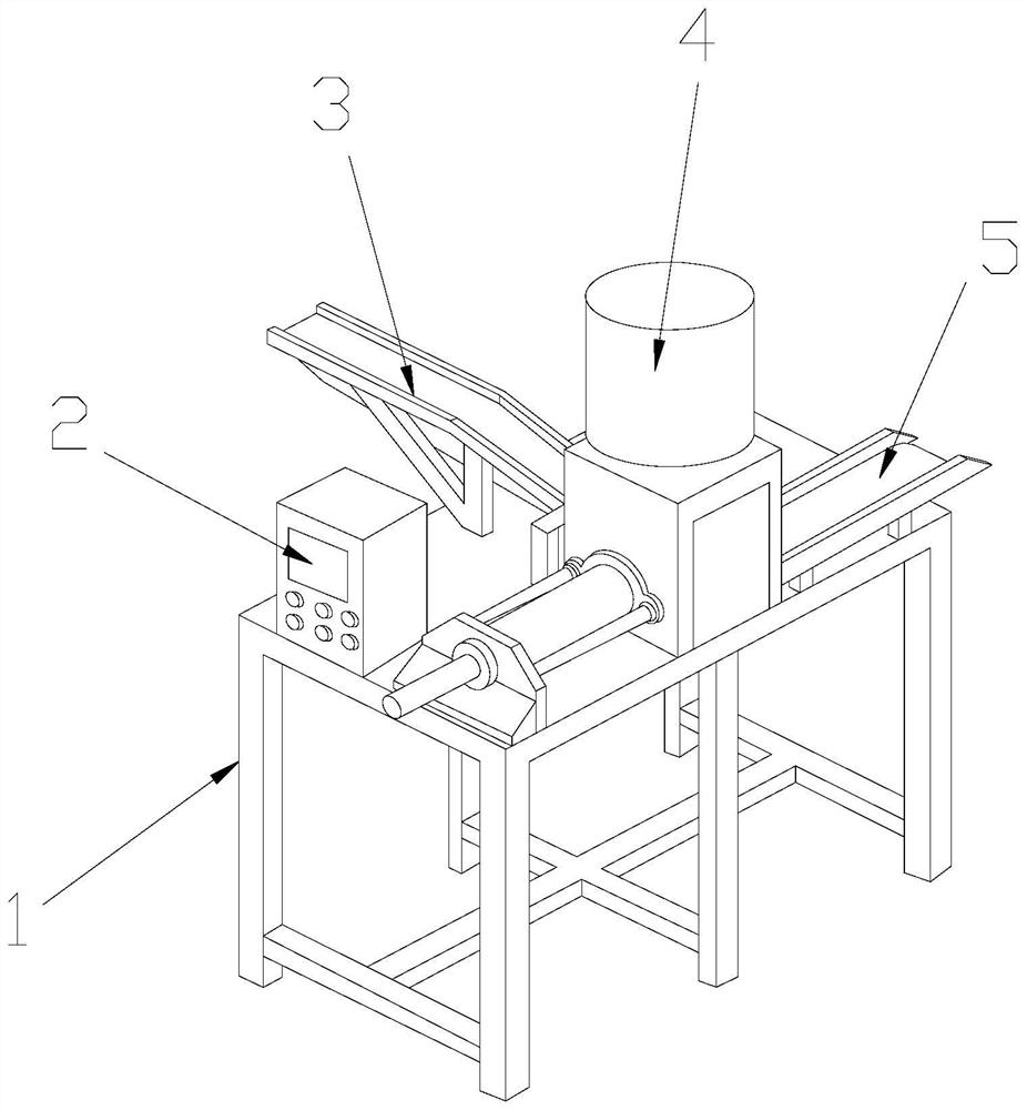
[0029] see Figure 1-Figure 3 , the present invention provides an angle cutting machine for easy diode processing, the structure of which includes a frame 1, an electric controller 2, a feeding and conveying device 3, an angle cutting machine 4, and an unloading device 5. The top of the frame 1 is in the middle There is a corner cutting machine 4 on the position, the frame 1 is connected with the corner cutting machine 4, the rear end of the corner cutting machine 4 is provided with a feeding conveying device 3, and the corner cutting machine 4 is connected to the upper The material conveying device 3 is matched, the right end of the angle cutter 4 is provided with a discharge device 5, the angle cutter 4 and the discharge device 5 are movably connected, and the top surface of the frame 1 is installed with a power supply. controller 2;
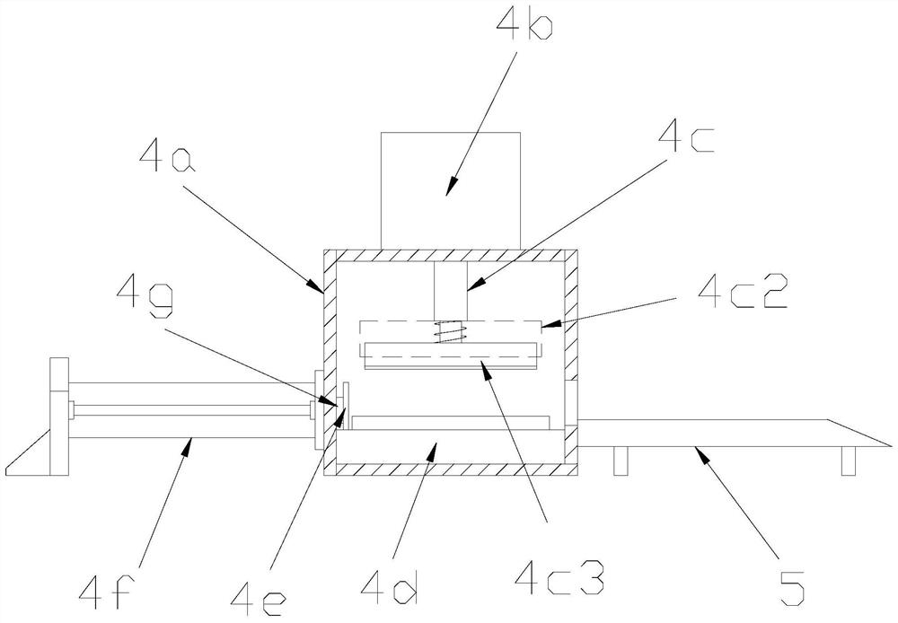
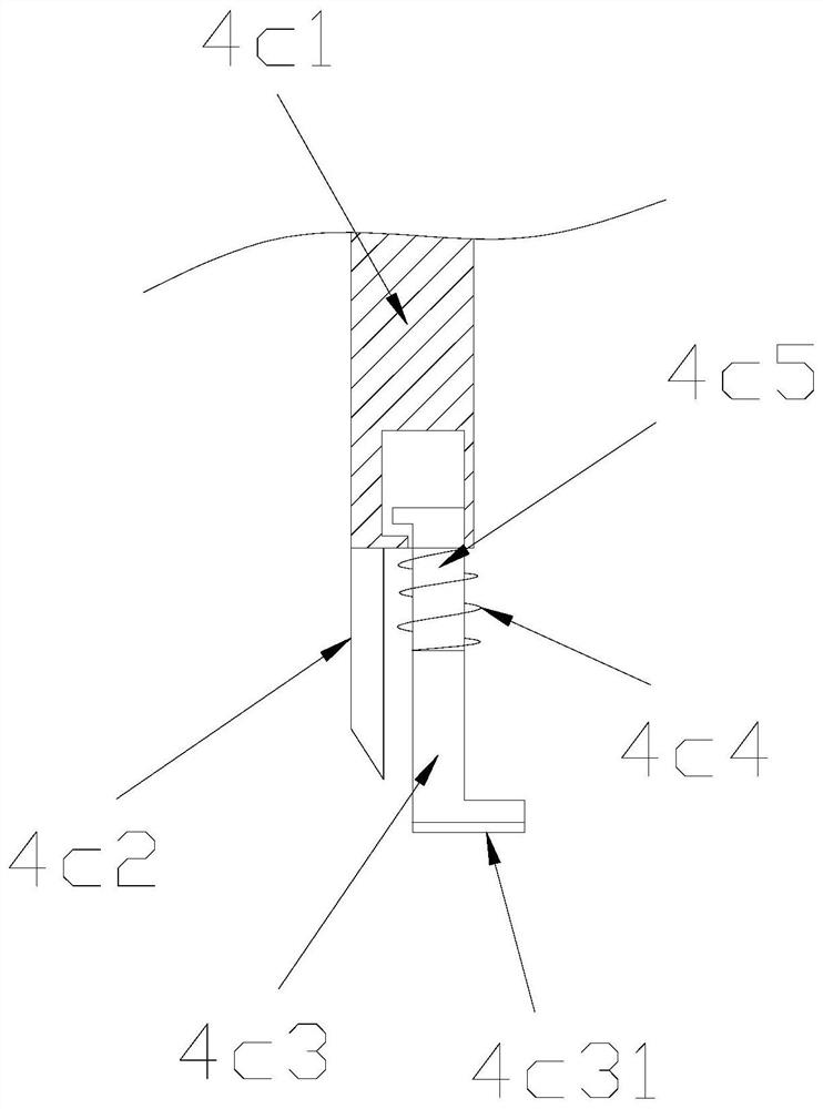
[0030] The angle cutting machine 4 is composed of a body 4a, a first air cylinder 4b, a side pressing and angle cutting mechanism 4c, a posi...
Embodiment 2
[0036] see Figure 1-Figure 5 , The present invention provides a chamfering machine for diode processing. The positioning table 4d also includes a knife groove 4d1, a scooping bucket 4d2, a fixing block 4d3, a threaded ring 4d4, and a pin length adjustment mechanism 4d5. The positioning There is a knife groove 4d1 on the surface of the working table 4d, a side surface of the positioning table 4d is provided with a scooping bucket 4d2, the positioning working table 4d and the scooping bucket 4d2 are movably connected, and the right end of the positioning working table 4d is There is a fixed block 4d3 on it, the positioning table 4d and the fixed block 4d3 are integrated structures, the surface of the fixed block 4d3 is provided with a pin length adjustment mechanism 4d5, the fixed block 4d3 and the pin length The adjusting mechanism 4d5 is threadedly connected by a threaded ring 4d4.
[0037] A buffer resistance band h1 is provided on the surface of the positioning table 4d, a...
PUM
 Abstract
Description
Claims
Application Information
 - R&D Engineer
- R&D Manager
- IP Professional
- Industry Leading Data Capabilities
- Powerful AI technology
- Patent DNA Extraction
Browse by: Latest US Patents, China's latest patents, Technical Efficacy Thesaurus, Application Domain, Technology Topic, Popular Technical Reports.
© 2024 PatSnap. All rights reserved.Legal|Privacy policy|Modern Slavery Act Transparency Statement|Sitemap|About US| Contact US: help@patsnap.com