
A method and device for detecting obstacle

A technology of obstacles and detection frames, applied in character and pattern recognition, image data processing, instruments, etc., can solve the problems of computing power consumption and high cost, and achieve the effects of saving costs, improving robustness, and saving computing resources

Pending Publication Date: 2020-09-01
APOLLO INTELLIGENT CONNECTIVITY (BEIJING) TECH CO LTD
View PDF12 Cites 13 Cited by
  • Summary
  • Abstract
  • Description
  • Claims
  • Application Information

AI Technical Summary

Problems solved by technology

The accuracy and real-time performance of this method can meet the requirements on better hardware, but it consumes computing power and the cost is relatively high

Method used


Image

  • A method and device for detecting obstacle
  • A method and device for detecting obstacle
  • A method and device for detecting obstacle

Examples


Embodiment Construction

[0020] Exemplary embodiments of the present application are described below in conjunction with the accompanying drawings, which include various details of the embodiments of the present application to facilitate understanding, and they should be regarded as exemplary only. Accordingly, those of ordinary skill in the art will recognize that various changes and modifications of the embodiments described herein can be made without departing from the scope and spirit of the application. Also, descriptions of well-known functions and constructions are omitted in the following description for clarity and conciseness.

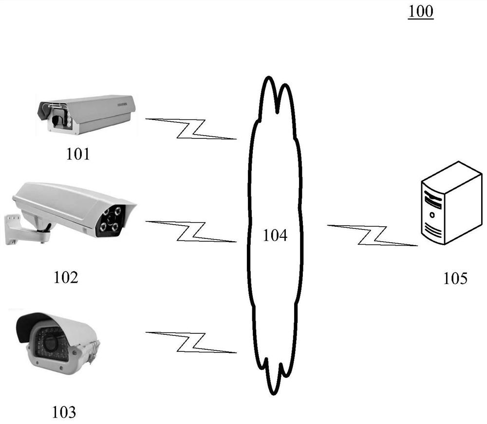
[0021] figure 1 An exemplary system architecture 100 is shown to which embodiments of the method for detecting obstacles or the apparatus for detecting obstacles of the present application can be applied.

[0022] Such as figure 1 As shown, system architecture 100 may include cameras 101 , 102 , 103 , network 104 and server 105 . The network 104 serves as a medium...


PUM


Abstract

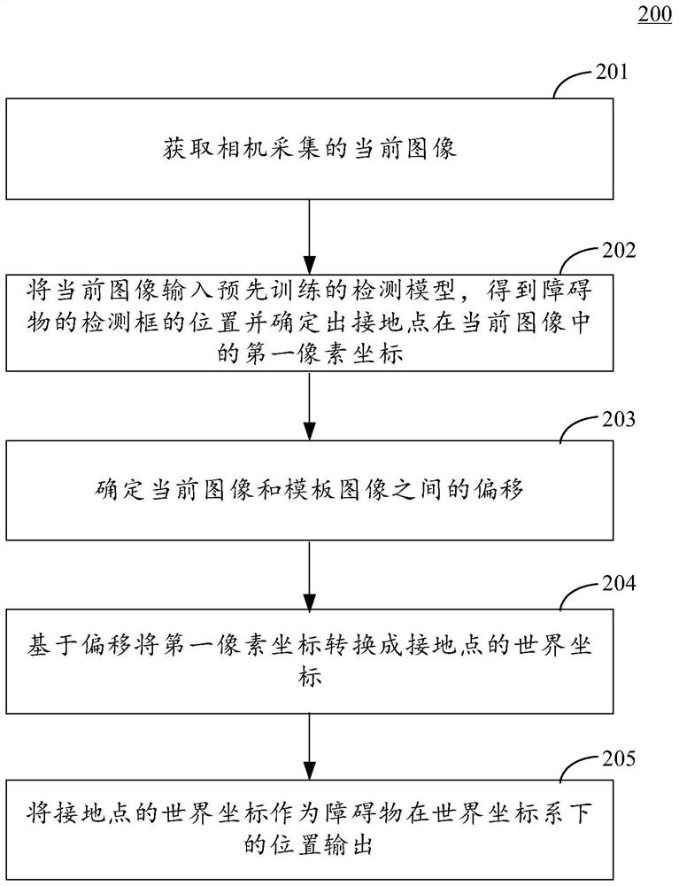
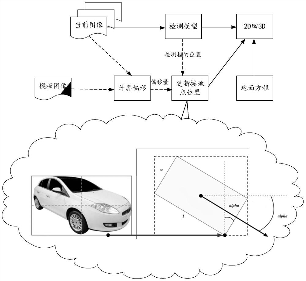
The invention discloses a method and device for detecting an obstacle, and relates to the technical field of intelligent transportation. The specific implementation scheme comprises the following steps of acquiring a current image collected by a camera; inputting the current image into a pre-trained detection model to obtain the position of a detection frame of the obstacle and determine a first pixel coordinate of the grounding point in the current image; determining offset between the current image and a template image, wherein the template image is an image used when external parameter calibration of the camera is carried out; converting the first pixel coordinates into world coordinates of the ground point based on the offset; and outputting the world coordinate of the grounding pointas the position of the obstacle in the world coordinate system. According to the embodiment, the problem of camera jittering is solved from the perspective of images, the robustness of a road side sensing system is greatly improved, and computing resources are saved.

Description

technical field [0001] The embodiments of the present application relate to the field of computer technology, in particular to the field of intelligent transportation technology. Background technique [0002] Roadside perception technology is a technology that sends perceived obstacles to vehicles through roadside sensors and perception algorithms, thereby helping vehicles realize automatic driving functions. Currently, roadside perception sensors include cameras and lidar. In the V2X (vehicle to everything, information exchange between the vehicle and the outside world) roadside perception scenarios, in order to obtain road traffic information beyond the line of sight through the camera, the camera is usually installed on a street light pole or a traffic light pole. The higher the camera, the larger the field of view obtained in the image, the more information, and the stronger the roadside perception. However, when the camera is mounted on a higher pole, the camera shakes...

Claims


Application Information

Patent Timeline
Patent Type & Authority Applications(China)
IPC IPC(8): G06T7/00G06T7/33G06T7/73G06T3/40G06T3/60G06K9/62G06T7/80G06V10/24
CPCG06T7/0002G06T7/33G06T7/73G06T3/4084G06T3/60G06T7/80G06T2207/10004G06T2207/20056G06T2207/30232G06T2207/20081G06T2207/20084G06T2207/30261G06V10/751G06F18/22G06T7/74G06T2207/30236G06V20/56G06V10/24G06V10/431G06T7/37G06V20/58G06F18/214
Inventor 贾金让
Owner APOLLO INTELLIGENT CONNECTIVITY (BEIJING) TECH CO LTD
Learn More