
Anti-collision system for bridge girder erection machine

A technology of anti-collision and bridge erecting machine, which is applied in the direction of erecting/assembling bridges, bridges, bridge construction, etc. It can solve the problems of easy collision, longer braking distance, lack of anti-collision measures, etc., and achieve safety and reliability High, small transmission delay, high degree of automation effect

Active Publication Date: 2020-09-01
内蒙古交通设计研究院有限责任公司
View PDF8 Cites 3 Cited by
  • Summary
  • Abstract
  • Description
  • Claims
  • Application Information

AI Technical Summary

Problems solved by technology

[0005] The first is that the structure of the bridge erecting machine is different from that of ordinary bridge erecting machines. The front outriggers, middle outriggers, rear outriggers and temporary outriggers of the bridge erecting machine run on the same track. The above invention lacks different devices on the same track. anti-collision measures;
[0006] The second is that the above-mentioned inventions only limit the limit position of the cart and the trolley, but there is no limit speed limit measure, but when the speed of the cart and trolley is too fast, the braking distance becomes longer after the limit position is exceeded, which is also easy to occur. collision

Method used


Image

  • Anti-collision system for bridge girder erection machine
  • Anti-collision system for bridge girder erection machine
  • Anti-collision system for bridge girder erection machine

Examples


Embodiment Construction

[0033] The implementation of the present invention will be described in detail below with examples, so as to fully understand and implement the implementation process of how the present invention uses technical means to solve technical problems and achieve technical effects.

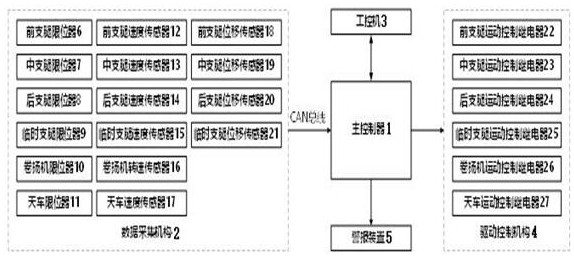
[0034] The invention discloses an anti-collision system for a bridge erecting machine, the structure is as follows figure 1 shown, including:

[0035] The main controller 1 is used to diagnose collision faults and send alarms and motion commands; the main controller 1 is equipped with a collision fault diagnosis program and an anti-collision control program, which is used for collision fault diagnosis and intelligent control of anti-collision;

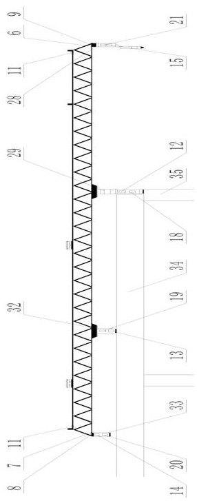
[0036] The data collection mechanism 2 is connected to the main controller 1 through the CAN bus, and is used to collect the position, speed and displacement of the front outrigger 29, the middle outrigger 32, the rear outrigger 33, the temporary outrigger 28, th...


PUM


Abstract

The invention discloses an anti-collision system for a bridge girder erection machine. The system involves a main controller, a data acquisition mechanism, an industrial personal computer, a drive control mechanism and an alarm device; the main controller is used for diagnosing collision faults and sending alarm and motion instructions; the data acquisition mechanism is connected with the main controller through a CAN bus and used for acquiring position, speed and displacement signals of a front supporting leg, a middle supporting leg, a rear supporting leg, a temporary supporting leg, a winchand a crown block and sending the signals to the main controller; the industrial personal computer is connected with the main controller and used for receiving the signals sent by the main controllerfor real-time monitoring and sending an emergency braking instruction to the main controller; the drive control mechanism is connected with the main controller and used for receiving a motion instruction sent by the main controller and used for motion control and drive of the front supporting leg, the middle supporting leg, the rear supporting leg, the temporary supporting leg, the winch and thecrown block; and the alarm device is connected with the main controller and used for receiving a danger alarm instruction sent by the main controller and giving an alarm. The system is specially designed for the bridge girder erection machine and has the characteristics of safety, reliability, high reaction speed and high real-time performance.

Description

technical field [0001] The invention belongs to the technical field of crane safety protection, and in particular relates to an anti-collision system for a bridge erecting machine. Background technique [0002] The bridge erecting machine is a kind of bridge crane, which is specially used to hoist the prefabricated reinforced concrete box girder to the bridge pier. Because of the high efficiency of the bridge erecting machine, it is widely used in the bridge construction of railways and highways. The main working process of the bridge erecting machine is as follows: the bridge erecting machine first uses temporary outriggers and rear outriggers to support, moves the front outrigger to the next pier and fixes it, and supports the front of the main girder together with the middle outrigger at the previous pier. After the main girder moves forward and is in place, it is supported by the rear outriggers, and the front and middle outriggers are released in turn, and the main gird...

Claims


Application Information

Patent Timeline
Patent Type & Authority Applications(China)
IPC IPC(8): B66C15/06B66C15/04B66C13/46B66C13/48E01D21/00
CPCB66C15/06B66C15/045B66C13/46B66C13/48E01D21/00
Inventor 李军王鹏李吉富
Owner 内蒙古交通设计研究院有限责任公司
Learn More