
High-power fiber laser indication light protection device and implementation method thereof

A fiber laser and protection device technology, applied in the direction of fiber mechanical structure, optical waveguide coupling, etc., can solve the problems of weak stability, complex structure, inability to effectively strip reverse fiber core light and cladding light, etc. The effect of protection from damage

Active Publication Date: 2020-08-28
GW (SHANGHAI) LASER TECH CO LTD
View PDF8 Cites 1 Cited by
  • Summary
  • Abstract
  • Description
  • Claims
  • Application Information

AI Technical Summary

Problems solved by technology

However, fiber optic circulators cannot isolate pump light and signal light of different wavelengths at the same time.
The dichroic mirror is due to the introduction of a spatial structure, which makes the system less stable than the all-fiber structure. The indicator light protection device with the all-fiber structure has a simple structure and high stability, but it is difficult to strip the reverse core light at present, and cannot Effectively strips opposite core and cladding light
[0005] Therefore, the existing fiber laser indicator light protection device cannot simultaneously strip the reverse fiber core signal light and cladding signal light at the same time, and has a complex structure and high cost, which is not suitable for mass production of high-power fiber lasers.

Method used


Image

  • High-power fiber laser indication light protection device and implementation method thereof
  • High-power fiber laser indication light protection device and implementation method thereof
  • High-power fiber laser indication light protection device and implementation method thereof

Examples


Embodiment approach

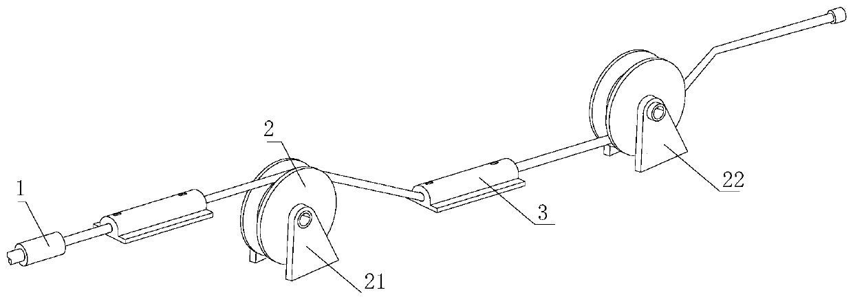
[0044] see Figure 8 , in order to better show the process of indicating light protection, this embodiment now proposes an implementation method of a high-power fiber laser indicating light protection device, including the following steps:

[0045] Step 1: In the working state, the core light generated by the pointing light laser 1 is transmitted in the fiber core 41. The pointing light emitted by the pointing light laser 1 and the reverse light have different wavelength characteristics, and the angle generated by the total reflection It is also different. When the angle of the incident light through the core light reaches or exceeds a certain angle, when the core 41 is transmitted to the receiving end, part of the core light will continue to reflect and return to the indicating light laser 1 to generate reverse core light. And cladding light, which indicates that the light emitted by the optical laser 1 has a monochromatic light with a wavelength of visible light in the fiber...


PUM


Abstract

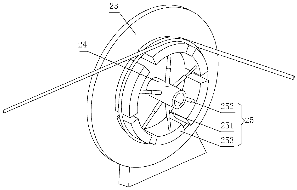
The invention discloses a high-power fiber laser indication light protection device and an implementation method thereof, and belongs to the fiber laser field; the device comprises an indicating lightlaser, optical fiber winding mechanisms and cladding light stripping mechanisms, an optical fiber connected to the indicating light laser is connected with the two sets of optical fiber winding mechanisms and the cladding light stripping mechanisms, the optical fiber winding mechanisms are used for changing the winding diameter of an optical fiber and the bending angle change of the optical fiber, fiber core light in the optical fiber enters a cladding from a fiber core, and the optical fiber winding mechanisms convert the fiber core light into cladding light. Reverse fiber core light and cladding light of the high-power optical fiber laser can be effectively stripped through two cladding light stripping mechanisms and step-by-step stripping, the indication light laser is protected against damage, and attenuation of the intensity of indication light cannot be caused.

Description

technical field [0001] The invention relates to the technical field of fiber lasers, in particular to a high-power fiber laser indicating light protection device and an implementation method thereof. Background technique [0002] High-power lasers are widely used in industrial processing and other fields due to their advantages such as good beam quality, high continuous power, good stability, small size, and easy movement. [0003] In high-power fiber lasers, forward and reverse bidirectional pumping is usually used. Due to the influence of the structure of the resonant cavity and the nonlinear effect in the cavity, the reverse signal light is very strong, and the power can reach tens or even hundreds of watts. The reverse signal light will cause damage to the indicator light device and destroy the use of the indicator light. Therefore, a reasonably designed and compact indicator light protection device is very important for high-power fiber lasers. [0004] At present, op...

Claims


Application Information

Patent Timeline
IPC IPC(8): G02B6/26G02B6/44
CPCG02B6/26G02B6/44
Inventor 张先明顾绣颖高放刘进辉丁进武
Owner GW (SHANGHAI) LASER TECH CO LTD
Learn More