An intelligent drill bit for real-time monitoring of drilling cutting force and its working method

A real-time monitoring and cutting force technology, which is applied to the automatic control system of drilling, drill bits, drilling equipment, etc., can solve the problems of undisclosed collection of cutting force, large interference factors, and limited detection accuracy, so as to improve the cutting pressure monitoring ability, Effectiveness to ensure monitoring results, good sealing and contact performance

Active Publication Date: 2022-08-02
SOUTHWEST PETROLEUM UNIV
View PDF8 Cites 0 Cited by
  • Summary
  • Abstract
  • Description
  • Claims
  • Application Information

AI Technical Summary

Problems solved by technology

[0004] Cutting force is an important physical quantity of the PDC bit in the rock breaking process, but the cutting force cannot be measured by the existing technology
At the same time, the existing test-while-drilling tools cannot provide the front-end information of the PDC bit when the rock is broken, and there is a certain lag in the identification of reservoir lithology
[0005] In view of the above problems, there are some related exploration schemes, such as the Chinese patent application number 201621181006.4, which provides a way to monitor the cutting torque in real time, but it is the thrust signal detected by the torque sensor, which has large interference factors and is difficult to detect. The precision is limited, and the Chinese patent application number 201810360236.4 discloses a device that can collect downhole mechanical parameters, but it does not disclose how to collect it, nor does it disclose whether cutting force can be collected

Method used


Image

  • An intelligent drill bit for real-time monitoring of drilling cutting force and its working method
  • An intelligent drill bit for real-time monitoring of drilling cutting force and its working method
  • An intelligent drill bit for real-time monitoring of drilling cutting force and its working method

Examples


Embodiment Construction

[0044]The present invention will be further described below in conjunction with the embodiments. It should be noted that in this paper, words such as "upper" and "lower" are only used to facilitate the description of the accompanying drawings, and do not limit the direction in actual use, and do not necessarily Any such actual relationship or order between these entities or operations is required or implied. Moreover, the terms "comprising", "comprising" or any other variation thereof are intended to encompass non-exclusive inclusion such that a process, method, article or device comprising a list of elements includes not only those elements, but also includes not explicitly listed or other elements inherent to such a process, method, article or apparatus.

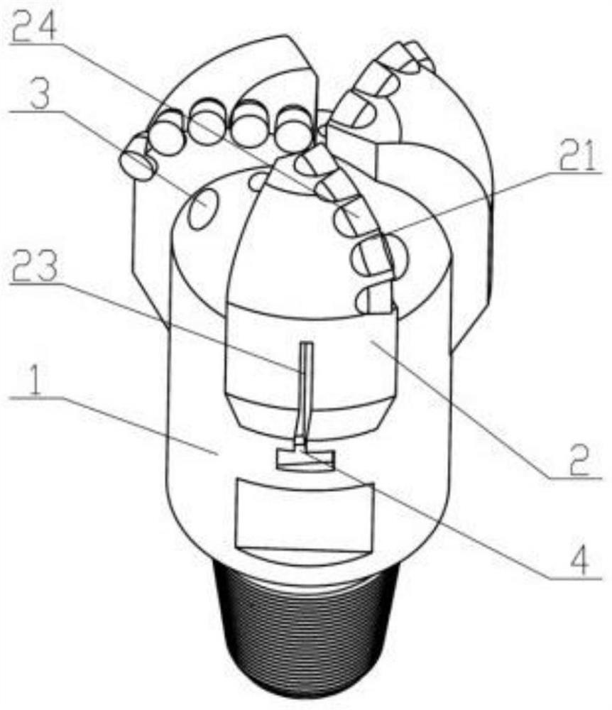
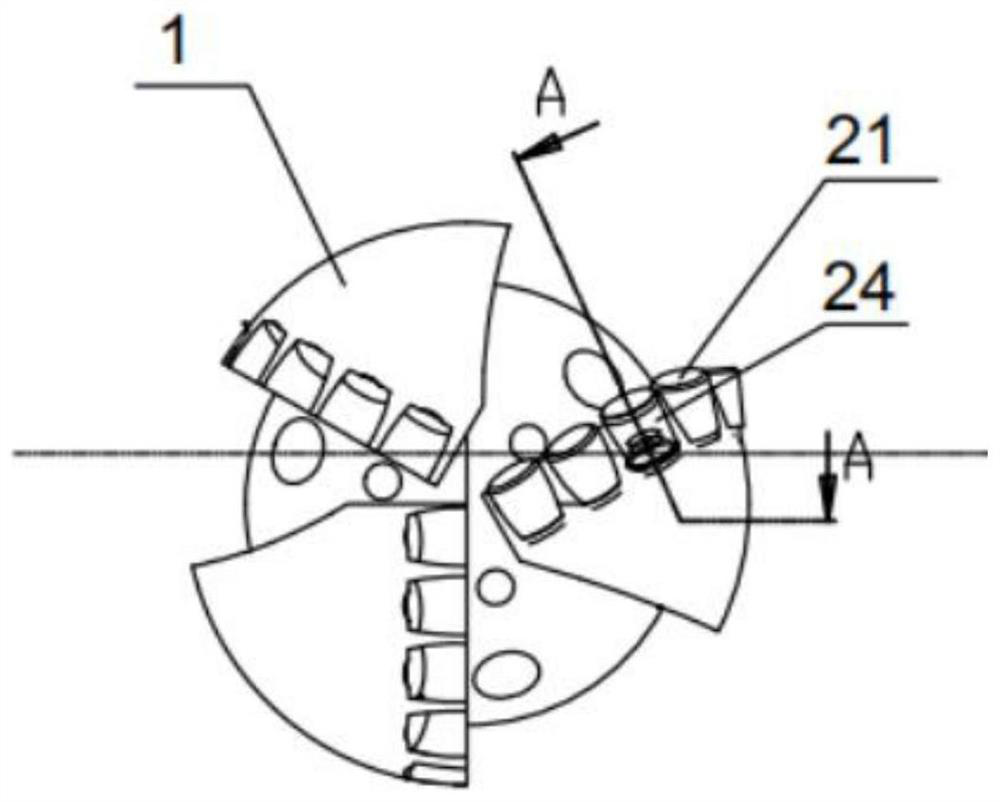
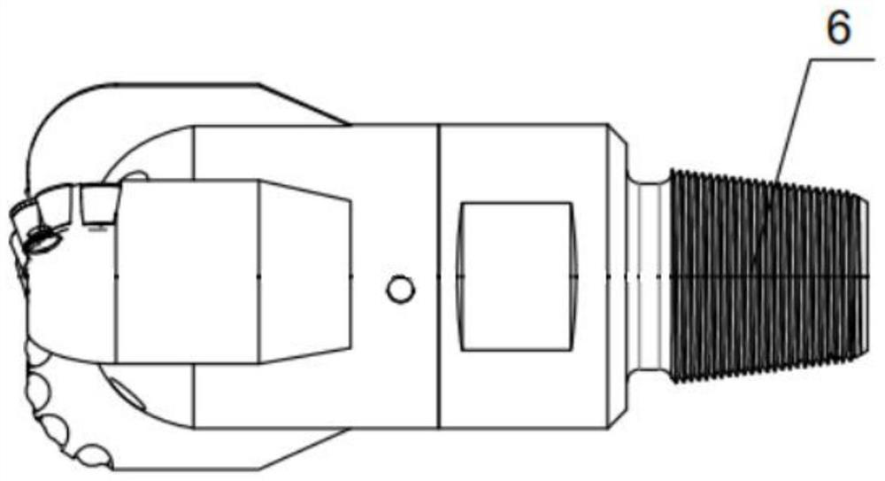
[0045] As shown in Figure 2, an intelligent drill bit for real-time monitoring of drilling cutting force includes a PDC drill bit body 1, a plurality of uniformly distributed blades 2 are arranged on the bit body, and each...


PUM


Abstract

The invention discloses an intelligent drill bit for real-time monitoring of drilling cutting force and a working method thereof, comprising a PDC drill bit body, a plurality of uniformly distributed PDC drill bit blades on the drill bit body, and belts on the cutting surface of the PDC bit blade blades There are installation holes, and a plurality of PDC drill cutting teeth are arranged in the installation holes. In each row of PDC drill cutting teeth, there is at least one pressure measuring cutting tooth; The middle part of the blade is provided with a through hole, which is used as a wiring groove. The lower part of the wiring groove is connected to the hollow cavity inside the nozzle, and the upper part is connected to the monitoring device of the pressure measuring cutting teeth; the wiring groove is provided with a wire and a signal conversion module, the wire The monitoring device is connected to the signal conversion module, and the signal conversion module is provided with a wireless signal transmitting device. By adding a monitoring device while drilling, the present invention can significantly improve the PDC bit's perception of formation rock characteristics, and provide strong technical support for directional drilling technology and sweet spot identification.

Description

technical field [0001] The invention relates to the technical field of drilling tools, in particular to an intelligent drill bit, in particular to an intelligent drill bit for real-time monitoring of drilling cutting force and a working method thereof. Background technique [0002] Drill bits are an essential tool in drilling engineering, used for geological exploration, oil and gas exploitation, water well drilling, etc. For different formations, drill bits with different structures and functions need to be selected. In the oil industry, with the increasing demand for unconventional oil and gas resources, the corresponding drilling technology and equipment are also gradually developing, among which the main function of the drill bit is to break the rock and form a wellbore. At present, drill bits can be divided into three types: diamond bits, roller cone bits and scraper bits. In addition, there are some new drill bits developed on the basis of these three bits. [0003] P...

Claims


Application Information

Patent Timeline
Patent Type & Authority Patents(China)
IPC IPC(8): E21B44/00E21B10/42
CPCE21B44/00E21B10/42
Inventor 蔡灿曹煜磊杨迎新谢冲李邦润
Owner SOUTHWEST PETROLEUM UNIV
Why Eureka
Try Eureka