
Road vehicle passing height limiting device and control system thereof

A road vehicle and control system technology, applied in the field of road vehicle traffic height limit device and its control system, can solve the problems of height monitoring, damage, waste, etc., and achieve the effect of improving monitoring efficiency, facilitating control, and facilitating monitoring

Inactive Publication Date: 2020-08-28
安徽倍斯特交通科技有限公司
View PDF8 Cites 0 Cited by
  • Summary
  • Abstract
  • Description
  • Claims
  • Application Information

AI Technical Summary

Problems solved by technology

[0003] The height measurement of the existing limited overhead is inaccurate and cannot transmit real-time height data to the remote control center; it is very inconvenient to monitor its height
The current limited elevated height reminder can only be a stylistic reminder that when a vehicle breaks into the limited elevated, the limited elevated will be damaged. If no one is on the scene after the damaged elevated, it will cause the vehicle involved in the accident to escape and even affect the safe driving of subsequent vehicles; Every time the slide bar of the height limiter is damaged, it needs to be replaced with a new one, resulting in waste
Although radio control is used to adjust the height of the existing limited elevated to the restricted elevated, the effective distance will not exceed 20 meters, which means that if you want to restrict the passage of vehicles, you must ask the staff to adjust the height of the restricted elevated

Method used


Image

  • Road vehicle passing height limiting device and control system thereof
  • Road vehicle passing height limiting device and control system thereof
  • Road vehicle passing height limiting device and control system thereof

Examples


Embodiment Construction

[0031] The following will clearly and completely describe the technical solutions in the embodiments of the present invention with reference to the accompanying drawings in the embodiments of the present invention. Obviously, the described embodiments are only some, not all, embodiments of the present invention. Based on the embodiments of the present invention, all other embodiments obtained by persons of ordinary skill in the art without creative efforts fall within the protection scope of the present invention.

[0032] In the description of the present invention, it should be understood that the terms "opening", "upper", "middle", "length", "inner", etc. indicate orientation or positional relationship, and are only for the convenience of describing the present invention and simplifying the description , rather than indicating or implying that the components or elements referred to must have a particular orientation, be constructed and operate in a particular orientation, an...


PUM


Abstract

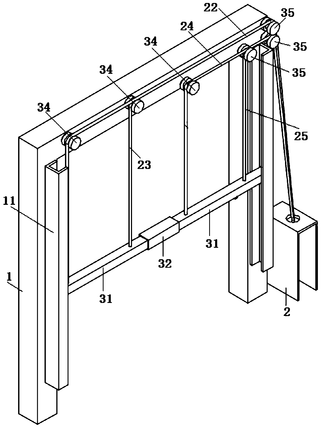
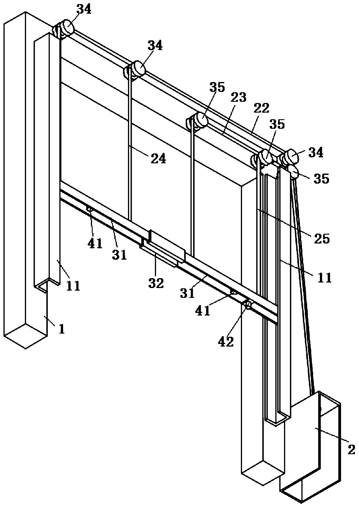
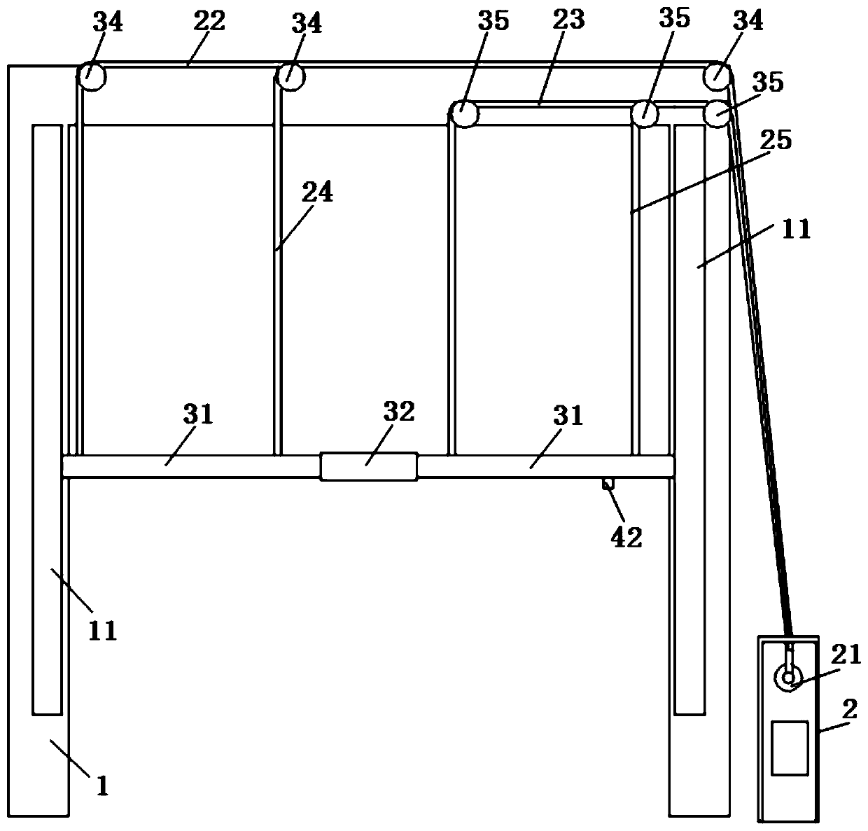
The invention discloses a road vehicle passing height limiting device and a control system thereof, and relates to the technical field of intelligent transportation. The device comprises a portal frame, a sliding rod structure and a control box; first U-shaped sliding rails are vertically installed on two vertical arms of the portal frame, wherein the openings of the two first U-shaped sliding rails are opposite; the two ends of the sliding rod structure are correspondingly installed in the two first U-shaped sliding rails in a sliding mode; the two ends of the rubber connecting block are connected with sliding rods; the first connecting rope and the third connecting rope bypass the first pulley and are respectively connected with two ends of one of the sliding rods; the second connectingrope and the fourth connecting rope bypass the second pulley to be connected with the two ends of the other sliding rod. The height of the sliding rod is accurately measured through the ks103 height measuring module and transmitted to the control panel, the short-range control terminal and the remote control terminal, so that the height of the sliding rod is reflected more finely and accurately, and monitoring of workers is facilitated; in addition, the infrared geminate transistors realize timely and accurate transmission of the sliding rod collision by the detection machine, so that the device is convenient and practical.

Description

technical field [0001] The invention belongs to the technical field of intelligent transportation, in particular to a road vehicle height limiting device and a control system thereof. Background technique [0002] The existing limited overhead is a device that limits the height of road vehicles. It is composed of gantry frame, cross bar, motor device and other components. It is widely used in various viaducts, expressways and other places where the height limit of vehicles is required. Existing height-limiting racks cannot accurately measure the height of the limit, and mostly rely on the naked eye to judge or use line marking. In order to prevent over-height vehicles from colliding with the limited elevated shelf, the existing limited elevated shelf often uses text to remind the current allowable passing height. The height of the existing limited elevated cross bar is mostly controlled by manual buttons to control its up, down, and stop or wireless remote control to cont...

Claims


Application Information

Patent Timeline
Patent Type & Authority Applications(China)
IPC IPC(8): E01F13/04H04L29/08
CPCE01F13/048H04L67/125
Inventor 赵德合
Owner 安徽倍斯特交通科技有限公司
Learn More