Health monitoring system and method for UPS vehicle

A technology of health monitoring system and power supply vehicle, applied in the direction of control device, etc., can solve the problems of inability to real-time monitoring of UPS power supply vehicle, poor user experience, and high cost

Active Publication Date: 2020-08-28
BEIJING HONGHUI INT ENERGY TECH DEV CO LTD
View PDF9 Cites 0 Cited by
  • Summary
  • Abstract
  • Description
  • Claims
  • Application Information

AI Technical Summary

Problems solved by technology

[0002] At present, there is no health monitoring system for UPS (Uninterruptible Power System, uninterruptible power supply with energy storage device) power supply vehicles, and it is impossible to monitor UPS power supply vehicles in real time
Generally, it is repaired through regular maintenance or relying on experience. During the regular maintenance process, if the internal components are broken, damaged or deformed, it will cause waste of resources to repair the internal components at this time; during the maintenance process based on experience, it will cause Inaccurate data, high cost, poor user experience

Method used


Image

  • Health monitoring system and method for UPS vehicle
  • Health monitoring system and method for UPS vehicle
  • Health monitoring system and method for UPS vehicle

Examples


Embodiment 1

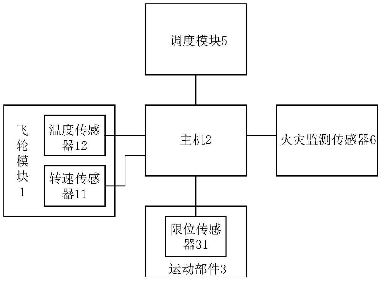
[0043] figure 1 It is a schematic diagram of a health monitoring system for a UPS power supply car provided by Embodiment 1 of the present invention.

[0044] refer to figure 1 , the system includes: a flywheel module 1, a host 2 and a moving part 3, wherein the flywheel module 1 includes a speed sensor 11 and a temperature sensor 12, and the moving part 3 is provided with a limit sensor 31;

[0045] The rotational speed sensor 11, the temperature sensor 12 and the limit sensor 31 are respectively connected with the host computer 2;

[0046] The rotational speed sensor 11 is used to collect the rotational speed of the flywheel to obtain the rotational speed value of the flywheel;

[0047] The temperature sensor 12 is used to collect the temperature of the flywheel to obtain the flywheel temperature value;

[0048] The limit sensor 31 is used to collect the wear of the moving parts to obtain the wear value;

[0049] Specifically, the speed sensor 11 can send the flywheel spee...

Embodiment 2

[0067] Figure 4 It is a flow chart of the health monitoring method for the UPS power supply car provided by Embodiment 2 of the present invention.

[0068] refer to Figure 4 , applied to the health monitoring system of the UPS power supply car as described above, the method comprises the following steps:

[0069] Step S101, collecting the rotational speed of the flywheel to obtain the rotational speed value of the flywheel;

[0070] Step S102, collecting the temperature of the flywheel to obtain the temperature value of the flywheel;

[0071] Step S103, collecting the wear of the moving parts to obtain the wear value;

[0072] Step S104, comparing the flywheel speed value with a preset speed threshold, and generating first fault information if the flywheel speed value reaches the preset speed threshold;

[0073] Step S105, comparing the flywheel temperature value with a preset temperature threshold, and generating second fault information if the flywheel temperature valu...


PUM


Abstract

The invention provides a health monitoring system and method for a UPS vehicle. The method comprises the steps that a rotating speed sensor collects the rotating speed of a flywheel to obtain a flywheel rotating speed value; a temperature sensor acquires the temperature of the flywheel to obtain a flywheel temperature value; a limiting sensor collects abrasion of the moving part to obtain an abrasion value; a host compares the flywheel rotating speed value with a preset rotating speed threshold value, and if the flywheel rotating speed value reaches the preset rotating speed threshold value, first fault information is generated; the flywheel temperature value is compared with a preset temperature threshold value, and if the flywheel temperature value reaches the preset temperature threshold value, second fault information is generated; the abrasion value is compared with a preset abrasion threshold, and if the abrasion value reaches the preset abrasion threshold, third fault information is generated; corresponding fault level processing is performed on the UPS vehicle according to the first fault information, the second fault information or the third fault information so that real-time monitoring can be performed on the UPS vehicle, the operation state of the UPS vehicle can be understood, and the accuracy of detection data and the user experience can be enhanced.

Description

technical field [0001] The invention relates to the technical field of UPS power supply vehicles, in particular to a health monitoring system and method for UPS power supply vehicles. Background technique [0002] At present, there is no health monitoring system for UPS (Uninterruptible Power System, uninterruptible power supply with energy storage device) power supply vehicle, and it is impossible to monitor the UPS power supply vehicle in real time. Generally, it is repaired through regular maintenance or relying on experience. During the regular maintenance process, if internal components are broken, damaged or deformed, repairing the internal components at this time will cause waste of resources; during the maintenance process based on experience, it will cause The data is inaccurate, the cost is high, and the user experience is poor. Contents of the invention [0003] In view of this, the purpose of the present invention is to provide a health monitoring system and m...

Claims


Application Information

Patent Timeline
Patent Type & Authority Applications(China)
IPC IPC(8): B60W50/02B60W50/14
CPCB60W50/02B60W50/0205B60W50/14B60W2050/146
Inventor 姜炜王佳良李光军汪大春秦坤王海彬
Owner BEIJING HONGHUI INT ENERGY TECH DEV CO LTD
Why Eureka
Try Eureka