
Equipment state monitoring application system

A technology of equipment status and electrical equipment, applied in the field of electric power, can solve the problems of lack of monitoring, low operation and maintenance efficiency, geographical dispersion, etc., and achieve the effect of reducing the number of equipment and improving the reliability of power consumption

Inactive Publication Date: 2018-08-17
GUANGDONG POWER GRID CO LTD +1
View PDF7 Cites 1 Cited by
  • Summary
  • Abstract
  • Description
  • Claims
  • Application Information

AI Technical Summary

Problems solved by technology

It is not only the most basic unit at the bottom of the distribution network, but also one of the key links for power transmission from high voltage to low voltage. The safe operation of its power facilities is very critical. In recent years, with the comprehensive transformation and Due to the continuous increase in the number of substations and distributions, most of the substations and distributions have a low degree of intelligence and scattered geographical locations. In the current situation of limited manpower and material resources for operation and maintenance, the inspection cycle is long. There are problems such as blind spots and lack of monitoring during the inspection process
Only relying on the traditional mode of manual regular inspection, the operation and maintenance efficiency is low, and it is impossible to form effective process data records and process analysis
There are certain security risks

Method used


Image

  • Equipment state monitoring application system

Examples


Embodiment Construction

[0023] The attached drawings are only for illustrative purposes, and cannot be understood as a limitation of this patent;

[0024] In order to better illustrate this embodiment, some parts of the drawings may be omitted, enlarged or reduced, and do not represent the size of the actual product;

[0025] For those skilled in the art, it is understandable that some well-known structures in the drawings and their descriptions may be omitted.

[0026] The technical solution of the present invention will be further described below in conjunction with the drawings and embodiments.

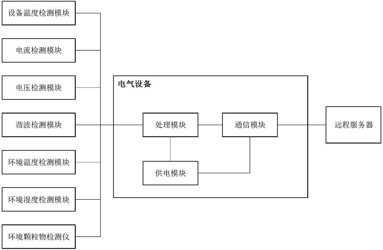
[0027] An application system based on equipment condition monitoring, such as figure 1 Shown, including: equipment temperature detection module, current detection module, voltage detection module, harmonic detection module, processing module, communication module and remote server;

[0028] The equipment temperature detection module, current detection module, voltage detection module, harmonic detection module and...


PUM


Abstract

The invention discloses equipment state monitoring application system. The system comprises an equipment temperature detection module, a current detection module, a voltage detection module, a harmonic detection module, a processing module, a communication module and a remote server; the equipment temperature detection module, the current detection module, the voltage detection module, the harmonic detection module and the communication module are all electrically connected with the processing module, and the communication module is in signal connection with the remote server; the equipment temperature detection module, the current detection module, the voltage detection module and the harmonic detection module are sequentially arranged on the surface of electrical equipment; the processing module and the communication module are both arranged inside the electrical equipment, the electrical equipment is provided with a power supply module, and the power supply module is electrically connected with the processing module and the communication module. Through the cooperation of several detection devices and modules and the remote server, real-time monitoring of the power consumption load and accurate prediction of the power consumption trend can be realized in time for power consumption of enterprises, and a strong support is provided for scientific power consumption of enterprises.

Description

Technical field [0001] The present invention relates to the field of electric power, and more specifically, to a monitoring and analyzing system for the operation state of electrical equipment of an electric enterprise. Background technique [0002] As the next level of the substation in the power system, the power distribution room of the power user is responsible for supplying high-voltage power to the surrounding power users. It is not only the most basic unit at the bottom of the distribution network, but also one of the key links in the transmission of power from high voltage to low voltage. The safe operation of its power facilities is very important. In recent years, with the comprehensive transformation of power transmission, distribution and transformation networks, Due to the continuous increase in the number of substations and distributions, most substations and distributions are low in intelligence and geographically dispersed. In the current situation of limited oper...

Claims


Application Information

Patent Timeline
Patent Type & Authority Applications(China)
IPC IPC(8): G01R31/00
CPCG01R31/00
Inventor 郑志谦吴裕宙骆华梁永昌尹玉芬姚松根胡炜全单连秋单志球邓汉荣林少明
Owner GUANGDONG POWER GRID CO LTD
Learn More