Cleaning equipment for gear machining

A technology for cleaning equipment and gears, which is applied in the direction of cleaning methods using tools, cleaning methods and utensils, and cleaning methods using gas flow, etc., which can solve the problems of inconvenient centralized treatment of iron filings, inconvenient gear fixing, and inconvenient cleaning work. Achieve the effect of convenient centralized processing and easy cleaning

Active Publication Date: 2020-08-28
惠安县崇武镇兴钗茶具商行
View PDF5 Cites 5 Cited by
  • Summary
  • Abstract
  • Description
  • Claims
  • Application Information

AI Technical Summary

Problems solved by technology

[0004] The purpose of the present invention is to solve the problem that the cleaning equipment in the prior art often does not clean the gears comprehensively, so that the iron filings or dirt on the gears still remain and affect the use, and it is not convenient to fix the gears, and it is not convenient to carry out the cleaning work , and it is not convenient to carry out centralized processing of the cleaned iron filings, etc., and a gear processing cleaning equipment is proposed

Method used


Image

  • Cleaning equipment for gear machining
  • Cleaning equipment for gear machining
  • Cleaning equipment for gear machining

Examples


Embodiment 1

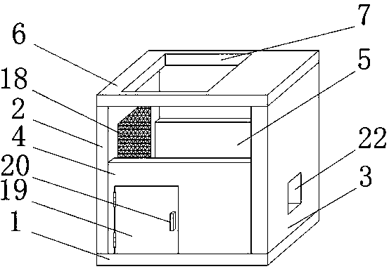
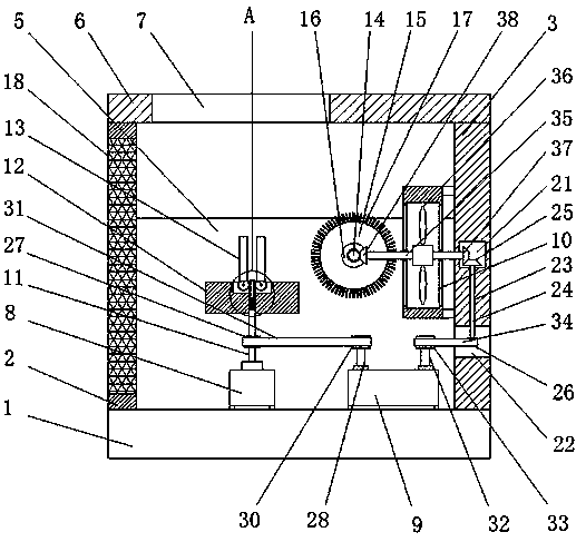
[0029] refer to Figure 1-5 , a gear processing and cleaning equipment, including a base 1, the top of the base 1 is fixedly connected with a first side plate 2 and a second side plate 3, and the side of the first side plate 2 and the second side plate 3 close to each other is fixed with a second side plate Both sides of the first baffle plate 4 and the second baffle plate 5, the bottoms of the first baffle plate 4 and the second baffle plate 5 are fixedly connected with the top of the base 1, and the tops of the first side plate 2 and the second side plate 3 are fixed The same top plate 6 is connected, and an operation port 7 is opened on the top plate 6. A motor 8 and a speed increaser 9 are fixedly installed on the top of the base 1. A fan housing 10 and a motor 8 are fixedly installed on one side of the second side plate 3. A rectangular shaft 11 is welded on the output shaft of the rectangular shaft 11. A fixed seat 12 is provided on the top of the rectangular shaft 11. T...

Embodiment 2

[0040] refer to Figure 1-5 , a gear processing cleaning equipment, including a base 1, the top of the base 1 is fixedly connected with a first side plate 2 and a second side plate 3 by welding, and the side of the first side plate 2 and the second side plate 3 close to each other passes through Both sides of the first baffle plate 4 and the second baffle plate 5 are welded and fixed, the bottoms of the first baffle plate 4 and the second baffle plate 5 are fixedly connected with the top of the base 1 by welding, the first side plate 2 and the second side plate The top of the side plate 3 is fixedly connected with the same top plate 6 by welding, the top plate 6 is provided with an operation port 7, the top of the base 1 is fixed with a motor 8 and a speed increaser 9 by bolts, and one side of the second side plate 3 passes through The fan casing 10 is fixedly installed with bolts, and the output shaft of the motor 8 is welded with a rectangular shaft 11. The top of the rectan...


PUM


Abstract

The invention belongs to the field of machining cleaning, particularly relates to cleaning equipment for gear machining. The cleaning equipment aims at solving the problems that existing cleaning equipment is frequently not comprehensive enough in gear cleaning, scrap iron or dirt on gears still remains, then use is affected, the gears are inconvenient to fix, cleaning work is inconvenient to carry out, and the cleared scrap iron and the like are inconvenient to treat in a centralized mode. According to the scheme, the cleaning equipment for gear machining comprises a base, a first side plateand a second side plate are fixedly connected to the top of the base, and the two sides of a first baffle and the two sides of a second baffle are fixed to the sides, close to each other, of the firstside plate and the second side plate. According to the cleaning equipment for gear machining, through the arrangement of fixing rods, a fixing base and fan blades, the cleaning equipment can clean the gears more comprehensively, scrap iron or dirt on the gears can be cleared away conveniently, the gears can be fixed conveniently, the cleaning work can be carried out conveniently, and the clearedscrap iron and the like can be conveniently treated in the centralized mode.

Description

technical field [0001] The invention relates to the technical field of processing and cleaning, in particular to a gear processing and cleaning equipment. Background technique [0002] Generally, in the process of gear processing, iron filings and other dirt will adhere to the surface more or less after grinding, especially for the gap between the teeth of the gear. If it is not cleaned in time, the iron filings or Dirt will adhere to the gears, so it needs to be cleaned to ensure the cleanliness of the gears and the accuracy of the gear meshing; [0003] However, the existing cleaning equipment is often not comprehensive enough to clean the gears, so that the iron filings or dirt on the gears still remain and affect the use, and it is not convenient to fix the gears, it is not convenient for the cleaning work to be carried out, and it is not convenient for cleaning out. Iron filings, etc. are processed in a centralized manner. Contents of the invention [0004] The purp...

Claims


Application Information

Patent Timeline
IPC IPC(8): B08B1/02B08B5/02B08B13/00
CPCB08B5/023B08B13/00B08B1/12B08B1/20Y02P70/10
Inventor 张斌庄锦芳
Owner 惠安县崇武镇兴钗茶具商行
Why Eureka
Try Eureka