
Current comparison circuit for overvoltage protection

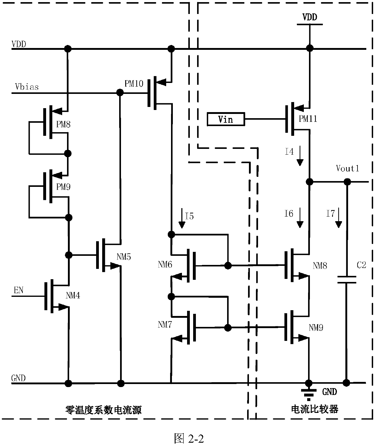
A current comparison, overvoltage protection technology, applied in the direction of measuring current/voltage, multiple input and output pulse circuits, measuring electricity, etc., can solve the Schmitt trigger threshold voltage change greatly, the reliability of the overvoltage protection function Low reliability, low reliability, etc., to avoid changes in overvoltage protection thresholds, reduce design complexity, and improve reliability.

Pending Publication Date: 2020-08-25
CHENGDU UNIV OF INFORMATION TECH
View PDF0 Cites 5 Cited by
  • Summary
  • Abstract
  • Description
  • Claims
  • Application Information

AI Technical Summary

Problems solved by technology

[0004] The comparison circuit for traditional overvoltage protection uses a Schmitt trigger as its output stage, and its upper threshold and lower threshold voltage settings are determined by the threshold voltage of the MOS tube. The threshold voltage is affected by factors such as process temperature, resulting in a Schmitt trigger. The threshold voltage of the trigger changes greatly, and the reliability is low; the comparison circuit used for traditional overvoltage protection, the reference current generation circuit of the input stage needs to be biased, the circuit is more complicated, and the threshold of overvoltage protection will vary under different operating temperatures. changes, resulting in less reliable overvoltage protection function

Method used


Image

  • Current comparison circuit for overvoltage protection
  • Current comparison circuit for overvoltage protection
  • Current comparison circuit for overvoltage protection

Examples


Embodiment Construction

[0035]In order to make the purpose, technical solutions and advantages of the embodiments of the present invention clearer, the technical solutions in the embodiments of the present invention will be clearly and completely described below in conjunction with the drawings in the embodiments of the present invention. Obviously, the described embodiments It is a part of embodiments of the present invention, but not all embodiments. The components of the embodiments of the invention generally described and illustrated in the figures herein may be arranged and designed in a variety of different configurations.

[0036] Accordingly, the following detailed description of the embodiments of the invention provided in the accompanying drawings is not intended to limit the scope of the claimed invention, but merely represents selected embodiments of the invention. Based on the embodiments of the present invention, all other embodiments obtained by persons of ordinary skill in the art wit...


PUM


Abstract

The invention discloses a current comparison circuit for overvoltage protection, and relates to the technical field of IC chips. The circuit comprises a current comparator which is used for convertinga voltage input signal into a current signal, comparing the current signal with a reference current signal and outputting an initial comparison result signal; a zero temperature coefficient current source coupled to the positive input side of the current comparator and used for generating a reference current signal; and a hysteresis comparator used for comparing the initial comparison result signal with a reference voltage signal and outputting a final comparison result signal. The reference voltage of the hysteresis comparator used by the circuit is provided by the reference voltage source and is not sensitive to the process and the working temperature, so that the change of the overvoltage protection threshold value of the hysteresis comparator at different working temperatures or the influence of the process angle in the chip manufacturing process can be avoided, and the reliability of the overvoltage protection function is improved; by adopting the hysteresis comparator, the anti-interference capability can be enhanced, and overvoltage reference voltage can be set and recovered.

Description

technical field [0001] The invention relates to the technical field of IC chips, in particular to a current comparison circuit for overvoltage protection. Background technique [0002] With the development of computer technology, multimedia technology, signal processing technology and microelectronics technology, the popularity of IC chips is getting higher and higher, which prompts great changes in the process, structure, performance and reliability requirements of IC chips. changes, and is developing towards high speed, low power consumption, small size, and on-chip integration. [0003] In terms of chip reliability design, the addition of an overvoltage protection module is the most important thing. Once the input voltage exceeds the internal withstand voltage limit of the chip, it will cause irreversible damage to the chip and greatly affect the service life of the chip. Therefore, the design of the overvoltage protection module has gradually become an integral part of ...

Claims


Application Information

Patent Timeline
Patent Type & Authority Applications(China)
IPC IPC(8): H03K5/24G01R19/165G01R1/30
CPCH03K5/2436G01R19/16576G01R19/16504G01R19/16519G01R1/30
Inventor 陈功练悦星肖楠李浩张涛魏华许祎李蠡董倩宇
Owner CHENGDU UNIV OF INFORMATION TECH
Learn More