High-power wireless charging magnetic coupling mechanism and electric energy transmission system thereof

A wireless charging and magnetic coupling technology, applied in transformer/inductor magnetic cores, circuits, inductors, etc., can solve the problems of heat dissipation without considering the magnetic coupling mechanism, poor magnetic shielding effect, low power density, etc. Quantitative and integrated design, reducing core loss, reducing the effect of volume

Active Publication Date: 2020-08-25
HUAZHONG UNIV OF SCI & TECH
View PDF5 Cites 0 Cited by
  • Summary
  • Abstract
  • Description
  • Claims
  • Application Information

AI Technical Summary

Problems solved by technology

[0003] At present, the magnetic coupling mechanism of high-power wireless charging mostly adopts a flat plate structure, that is, a whole planar magnetic core is attached to the back of a circular coil. This structure is simple in structure, and has better transmission efficiency and anti-offset characteristics. It does not make full use of the height of the coupling mechanism to strengthen the magnetic field in the height direction of the coupling mechanism, resulting in that although the coupling mechanism can be made thinner, its area is too large, the power density is low, the loss is large, and the magnetic shielding effect is poor. Most of them do not consider the heat dissipation of the magnetic coupling mechanism

Method used


Image

  • High-power wireless charging magnetic coupling mechanism and electric energy transmission system thereof
  • High-power wireless charging magnetic coupling mechanism and electric energy transmission system thereof
  • High-power wireless charging magnetic coupling mechanism and electric energy transmission system thereof

Examples


Embodiment Construction

[0033] In order to make the object, technical solution and advantages of the present invention more clear, the present invention will be further described in detail below in conjunction with the accompanying drawings and embodiments. It should be understood that the specific embodiments described here are only used to explain the present invention, not to limit the present invention. In addition, the technical features involved in the various embodiments of the present invention described below can be combined with each other as long as they do not constitute a conflict with each other.

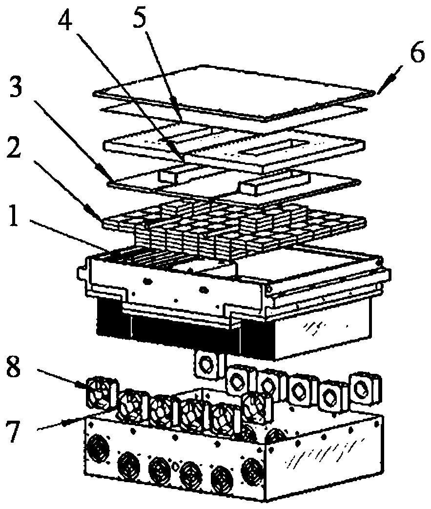
[0034] like figure 1 As shown, the embodiment of the present invention provides a high-power wireless charging magnetic coupling mechanism, including: a symmetrically distributed primary side mechanism and a secondary side mechanism; the primary side mechanism includes a heat sink assembly 1 and a magnetic core assembly distributed sequentially from bottom to top 2. Insulation plate assembly...


PUM

PropertyMeasurementUnit
lengthaaaaaaaaaa
widthaaaaaaaaaa
heightaaaaaaaaaa

Abstract

The invention discloses a high-power wireless charging magnetic coupling mechanism and an electric energy transmission system thereof, and belongs to the field of wireless charging. The magnetic coupling mechanism comprises a primary side mechanism and a secondary side mechanism, and the primary side mechanism and the secondary side mechanism are completely symmetrical. The primary side mechanismis sequentially provided with an aluminum housing heat dissipation cover, a draught fan, a heat dissipation device assembly, a magnetic core assembly, an insulating plate assembly, a coil layer, a silica gel layer and an insulating pressing plate from bottom to top, and power exceeding 100 kilowatts is wirelessly transmitted between the primary side mechanism and the secondary side mechanism. Thewireless charging magnetic coupling mechanism is applied to a high-energy-density transmission scene, and the primary side mechanism and the secondary side mechanism can still keep a high coupling coefficient level at a long distance, so that energy loss in the wireless charging process is reduced, meanwhile, the wireless charging magnetic coupling mechanism has excellent heat dissipation performance and magnetic shielding performance, and light weight of high-power wireless charging is achieved.

Description

technical field [0001] The invention belongs to the technical field of wireless charging, and more specifically relates to a high-power wireless charging magnetic coupling mechanism and a power transmission system thereof. Background technique [0002] Electromagnetic induction wireless charging has been widely and maturely applied in electric vehicles, but the current power is only at the kilowatt level. For high-power wireless charging systems with a power exceeding 100 kilowatts, the wireless charging magnetic coupling mechanism is required to have a high power density, and a compact and simple structure, which requires high system stability. In order to reduce magnetic flux leakage, the requirements for magnetic shielding Also taller. [0003] At present, the magnetic coupling mechanism of high-power wireless charging mostly adopts a flat plate structure, that is, a whole planar magnetic core is attached to the back of a circular coil. This structure is simple in struct...

Claims


Application Information

Patent Timeline
Patent Type & Authority Applications(China)
IPC IPC(8): H01F38/14H01F27/24H01F27/28H01F27/32H01F27/08H02J50/10
CPCH01F27/085H01F27/24H01F27/28H01F27/324H01F38/14H02J50/10
Inventor 刘邦银朱金炜李其琪徐炜钰
Owner HUAZHONG UNIV OF SCI & TECH
Why Eureka
Try Eureka