Hydraulic control valve set

A technology of hydraulic control valves and control holes, which is applied to fluid pressure actuation system components, servo motor components, fluid pressure actuation devices, etc., and can solve the problems of hydraulic control valve group occupation and large installation space

Pending Publication Date: 2020-08-25
WUHAN MARINE MACHINERY PLANT
View PDF11 Cites 0 Cited by
  • Summary
  • Abstract
  • Description
  • Claims
  • Application Information

AI Technical Summary

Problems solved by technology

[0004] The embodiment of the present disclosure provides a hydraulic control valve group, which can solve the problem that the hydraulic control valve group occupies a large amount of installation space

Method used


Image

  • Hydraulic control valve set
  • Hydraulic control valve set
  • Hydraulic control valve set

Examples


Embodiment Construction

[0042] In order to make the purpose, technical solution and advantages of the present disclosure clearer, the implementation manners of the present disclosure will be further described in detail below in conjunction with the accompanying drawings.

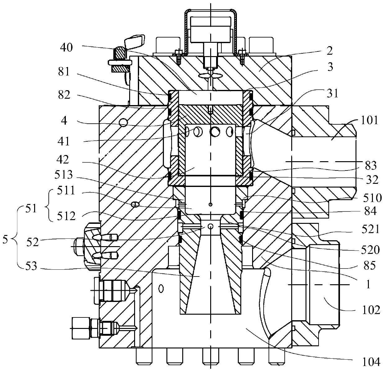
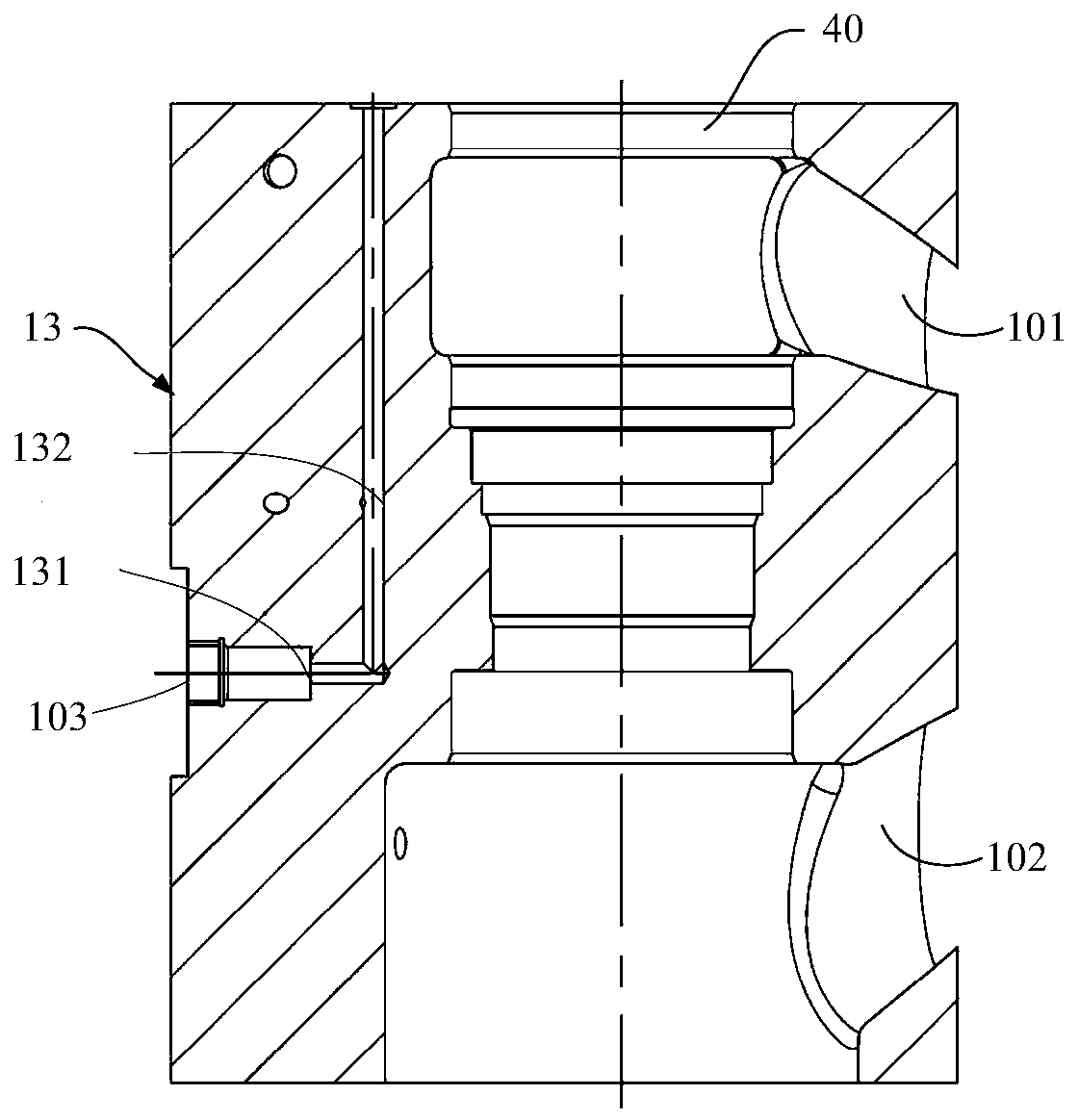
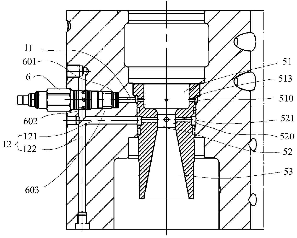
[0043]An embodiment of the present disclosure provides a hydraulic control valve group, such as figure 1 As shown, the hydraulic control valve group includes a valve body 1 and a valve cover 2 installed at one end of the valve body 1. The valve body 1 is provided with a main oil inlet 101, a main oil return port 102, and a main control oil port 103 (see figure 2 ) and connected to the oil port 104, the hydraulic control valve group also includes a valve sleeve 3, a valve core 4, a Venturi tube 5 and a directional valve 6 (see image 3 ), and the oil port 104 communicates with the main oil return port 102.

[0044] The valve sleeve 3 is fixedly inserted into the valve body 1 , and the valve sleeve 3 is provided with a control hole...


PUM


Abstract

The invention provides a hydraulic control valve set, and belongs to the field of hydraulic devices. The hydraulic control valve set comprises a valve body and a valve deck, wherein a main oil inlet,a main oil return opening, a main control oil opening and a communicating oil opening are formed in the valve body, the hydraulic control valve set further comprises a valve sleeve, a valve element, aVenturi tube and a direction valve, the valve sleeve is fixedly inserted into the valve body, one end of the valve element is sealed and arranged towards the valve deck to form a control cavity, theVenturi tube is inserted into the valve body, the Venturi tube comprises an inlet section, a middle section and an outlet section which sequentially extend backwards to the valve cover, the directionvalve is fixedly installed on the valve body, a first control oil port of the direction valve communicates with the inlet section, a second control oil port of the direction valve communicates with the middle section, a working oil port of the direction valve communicates with the control cavity, and when an oil pressure difference value between the first control oil port and the second control oil port is larger than a set threshold value of the direction valve, the working oil port communicates with the second control oil port. According to the hydraulic control valve set, the flow can be effectively controlled through the hydraulic control valve set.

Description

technical field [0001] The disclosure belongs to the field of hydraulic devices, in particular to a hydraulic control valve group. Background technique [0002] In the hydraulic system, the actuators are usually controlled by hydraulic control valve groups with different functions to realize various actions of the actuators. For example, when it is necessary to control the speed of the actuator, the hydraulic components such as the pressure reducing valve, the controllable throttle valve and the pressure compensator can be combined into a hydraulic control valve group through the oil pipe connection, so as to realize the control of the actuator by the hydraulic control valve group. speed control. [0003] However, since each hydraulic component has an independent valve body, the hydraulic control valve group is bulky and occupies a large amount of installation space. Moreover, since this type of hydraulic control valve group contains a large number of parts, and part of th...

Claims


Application Information

Patent Timeline
IPC IPC(8): F15B13/02F15B21/041
CPCF15B13/021F15B13/023F15B13/025F15B21/041
Inventor 洪威方敏
Owner WUHAN MARINE MACHINERY PLANT
Why Eureka
Try Eureka