Wind power blade demoulding hoisting clamp and wind power blade demoulding method

A technology for wind power blades and blades, which is applied in the field of wind power blade stripping lifting fixtures and wind power blade stripping, and can solve the problem of belt or spreader blade tripping, suspension belt or spreader not being able to effectively clamp the suspended blade, blade slipping, etc. problems, to achieve the effects of improving reliability and safety, improving blade demoulding efficiency, and elastically recovering the structure.

Active Publication Date: 2020-08-25
ZHUZHOU TIMES NEW MATERIALS TECH
View PDF6 Cites 2 Cited by
  • Summary
  • Abstract
  • Description
  • Claims
  • Application Information

AI Technical Summary

Problems solved by technology

[0002] At present, wind turbine blades are mostly hoisted by slings and ordinary slings. Because the slings or slings cannot effectively clamp the lifted blades, sometimes slings will appear during the air transfer process after the blades are lifted. Or when the sling is disconnected from the lifting blade, once the blade is disconnected and falls from the air, it will damage the blade and hit the equipment or personnel below, causing major safety accidents, which is extremely unsafe
[0003] The existing blade root lifting fixture is a C-shaped seat. Since the distance between the C-shaped seat is generally greater than the thickness of the blade root and does not have a self-locking function, there is a risk of the blade slipping during the demoulding process.
In the self-locking process, if the self-locking force is too large, and the contact surface between the fixture and the wind turbine blade is relatively small, the wind turbine blade, as a kind of FRP material, is relatively brittle and may easily cause crush damage

Method used


Image

  • Wind power blade demoulding hoisting clamp and wind power blade demoulding method
  • Wind power blade demoulding hoisting clamp and wind power blade demoulding method
  • Wind power blade demoulding hoisting clamp and wind power blade demoulding method

Examples


Embodiment Construction

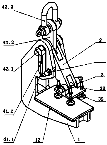
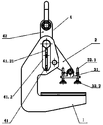
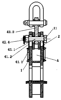
[0030] Attached below Figure 1~4 Embodiments of the present invention are described in detail.

[0031] The wind power blade stripping and lifting fixture includes a C-shaped seat 1, a slanted and swingable pressing block connecting rod 2 mounted on the C-shaped seat 1, and a lower end of the pressing block connecting rod 2 for pressing the blade on the C-shaped The pressing block assembly 3 on the seat 1 is characterized in that it also includes an elastic lifting assembly 4 that can drive the pressing block connecting rod 2 to swing. The elastic lifting assembly 4 is movably mounted on the C-shaped seat 1 and positions the pressing block by elastic force. The initial inclination angle of the connecting rod 2 maximizes the initial distance between the briquetting block assembly 3 and the C-shaped seat 1, and the blades extend between the C-shaped seat 1 and the briquetting block assembly 3, and are lifted up with the elastic lifting assembly 4 The blade gravity loads on the...


PUM


Abstract

The invention provides a wind power blade demoulding hoisting clamp. The wind power blade demoulding hoisting clamp comprises a C-shaped seat, a pressing block connecting rod obliquely arranged and installed on the C-shaped seat in a swinging mode and a pressing block assembly installed at the lower end of the connecting rod and used for compressing a blade on the C-shaped seat. The wind power blade demoulding hoisting clamp is characterized by further comprising an elastic hoisting assembly capable of driving the pressing block connecting rod to swing, the elastic hoisting assembly is movablyinstalled on the C-shaped seat and enables the initial spacing between the pressing block assembly and the C-shaped seat to be the largest through an initial oblique angle of an elastic positioning pressing block connecting rod, the blade extends between the C-shaped seat and the pressing block assembly, blade gravity is located on the C-shaped seat with the upward hoisting of the elastic hoisting assembly, and the pressing block connecting rod swings downwards with the hoisting of the elastic hoisting assembly to enable the spacing between the pressing block assembly and the C-shaped seat tobe reduced and pressed on the blade. According to the wind power blade demoulding hoisting clamp, the blade is effectively protected from being damaged in the demoulding process due to clamping, thereliability and safety of the clamp are improved, the demoulding efficiency of the blade is improved, and the service life is long.

Description

technical field [0001] The invention relates to a wind power blade stripping lifting fixture and a wind power blade stripping method, and belongs to the technical field of wind power blade stripping. Background technique [0002] At present, wind turbine blades are mostly hoisted by slings and ordinary slings. Because the slings or slings cannot effectively clamp the lifted blades, sometimes slings will appear during the air transfer process after the blades are lifted. Or the situation that the spreader and the lifting blade are tripped, once the blade is tripped and falls from the air, it will damage the blade and hit the equipment or personnel below, causing a major safety accident, which is extremely unsafe. [0003] The existing blade root lifting fixture is a C-shaped seat. Since the distance between the C-shaped seat is generally greater than the thickness of the blade root and does not have a self-locking function, there is a risk of the blade slipping during the dem...

Claims


Application Information

Patent Timeline
Patent Type & Authority Applications(China)
IPC IPC(8): B66C1/10B66C13/04B66C15/00
CPCB66C1/10B66C13/04B66C15/00
Inventor 曹阳俊林能发范阳舟解慧戴明亮张满闯
Owner ZHUZHOU TIMES NEW MATERIALS TECH
Why Eureka
Try Eureka