Dry desulfurization, denitrification and purification integrated device for kiln flue gas
A dry desulfurization and flue gas technology, used in gas treatment, furnaces, furnace components, etc., can solve problems such as inability to reduce industrial production costs, failure of thermal energy, and inability to recycle
- Summary
- Abstract
- Description
- Claims
- Application Information
AI Technical Summary
Problems solved by technology
Method used
Image


Examples
Embodiment 1
[0049] Such as Figure 1-8 As shown, an integrated device for dry desulfurization, denitrification and purification of flue gas from a kiln includes a desulfurization tower 1 connected with a flue gas heat energy recovery component 2 . The flue gas heat energy recovery component 2 is connected with several dehumidifiers 3 ; the dehumidifier 3 is connected with several SCR denitrification catalytic components 4 , and the SCR denitrification catalytic component 4 is connected with a chimney 5 . Specifically, after the flue gas is desulfurized by the desulfurization tower 1, the heat energy in the flue gas is recovered by the flue gas heat energy recovery component 2, and the flue gas is dried by the dehumidifier 3 to avoid a large amount of "smoke and rain" in the process of discharging the flue gas .
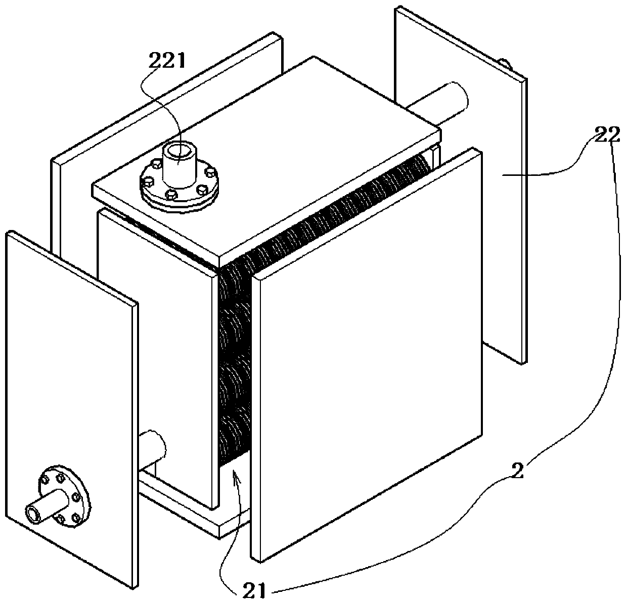
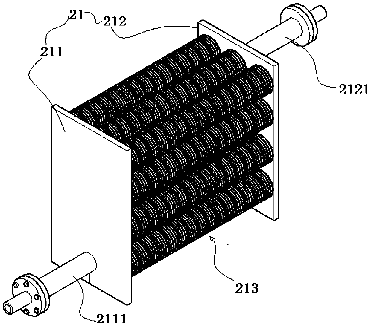
[0050] The specific structure of the flue gas heat energy recovery component 2 is as follows:
[0051] The flue gas heat energy recovery assembly 2 includes a heat energy recover...
Embodiment 2
[0060] Such as Figure 1-8 As shown, in this embodiment, on the basis of the structure of Embodiment 1, the flue gas heat energy recovery assembly 2 is connected with two dehumidifiers 3; the dehumidifiers 3 are connected in series; the dehumidifier 3 is connected with two dehumidifiers connected in series SCR denitrification catalytic component4.
[0061] It is realized that the flue gas after thermal energy recovery is subjected to secondary dehumidification through the dehumidifier 3 , and secondary denitrification treatment through the SCR denitrification catalytic component 4 .
[0062] Among them, the SCR denitration catalytic assembly 4 is a conventional SCR denitration catalytic device disclosed in the prior art, and its main structure includes an SCR denitration catalyst and a housing equipped with an SCR denitration catalyst. Catalytic denitrification to reduce nitrogen oxides in flue gas.
Embodiment 3
[0064] Such as Figure 1-8 As shown, in this embodiment, on the basis of the structure of Embodiment 2, the dehumidifier 3 is designed as the following structure to perform dehumidification.
[0065] The dehumidifier 3 includes a dehumidification shell, and the dehumidification shell has a dehumidification liquid. Specifically, the dehumidification liquid is dehumidified by using, for example, saturated calcium chloride or saturated calcium carbonate solution.
[0066] The dehumidification casing is sealed, and the dehumidification casing is provided with a smoke loosening cage part 31, and the smoke scattering cage part 31 is used to diffuse the flue gas, and the drying effect of the flue gas is improved by diffusing the flue gas.
[0067] The smoke diffuser cage part 31 includes a spiral smoke diffuser pipe 311, and several smoke diffuser spheres 312 are communicated with the spiral smoke diffuser tube 311. Several through holes. Several through holes are opened on the spi...
PUM
 Abstract
Description
Claims
Application Information
 - Generate Ideas
- Intellectual Property
- Life Sciences
- Materials
- Tech Scout
- Unparalleled Data Quality
- Higher Quality Content
- 60% Fewer Hallucinations
Browse by: Latest US Patents, China's latest patents, Technical Efficacy Thesaurus, Application Domain, Technology Topic, Popular Technical Reports.
© 2025 PatSnap. All rights reserved.Legal|Privacy policy|Modern Slavery Act Transparency Statement|Sitemap|About US| Contact US: help@patsnap.com