
Battery thermal management system based on heat pipe and liquid cooling device

A battery thermal management and cooling device technology, applied in secondary batteries, circuits, electrical components, etc., can solve the problem of high coolant temperature in the coolant outlet section, low coolant temperature in the coolant inlet section, and increased leakage points of the liquid cold plate. and other problems, to achieve uniform heat dissipation, improve heat exchange efficiency, and reduce flow power consumption.

Active Publication Date: 2020-08-21
GEELY AUTOMOBILE INST NINGBO CO LTD +1
View PDF16 Cites 1 Cited by
  • Summary
  • Abstract
  • Description
  • Claims
  • Application Information

AI Technical Summary

Problems solved by technology

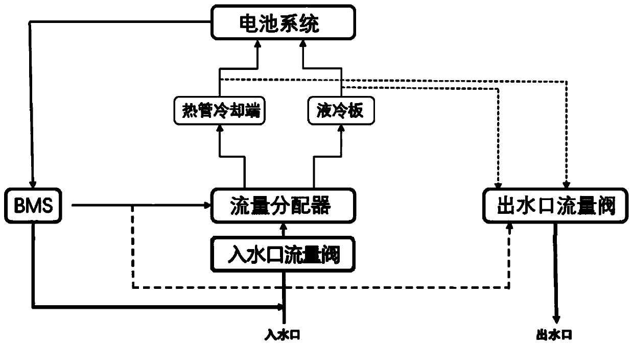
[0007] The technical problem to be solved by the present invention is that the prior art uses a liquid cold plate, but when the liquid cold plate is installed on the side of the battery module, it needs to be fixed on the side, and the temperature of the cooling liquid at the inlet section of the cooling liquid is low, and the heat exchange effect is good. The temperature of the coolant in the section is high, the heat transfer effect is poor, and there is a temperature difference between the water inlet and outlet. In addition, the gap between the modules is small, and the use of a liquid cooling plate will increase the leakage point. A battery thermal management system based on heat pipes and liquid cooling devices is provided. A battery thermal management system based on a heat pipe and a liquid cooling device includes:

Method used


Image

  • Battery thermal management system based on heat pipe and liquid cooling device
  • Battery thermal management system based on heat pipe and liquid cooling device
  • Battery thermal management system based on heat pipe and liquid cooling device

Examples


Embodiment

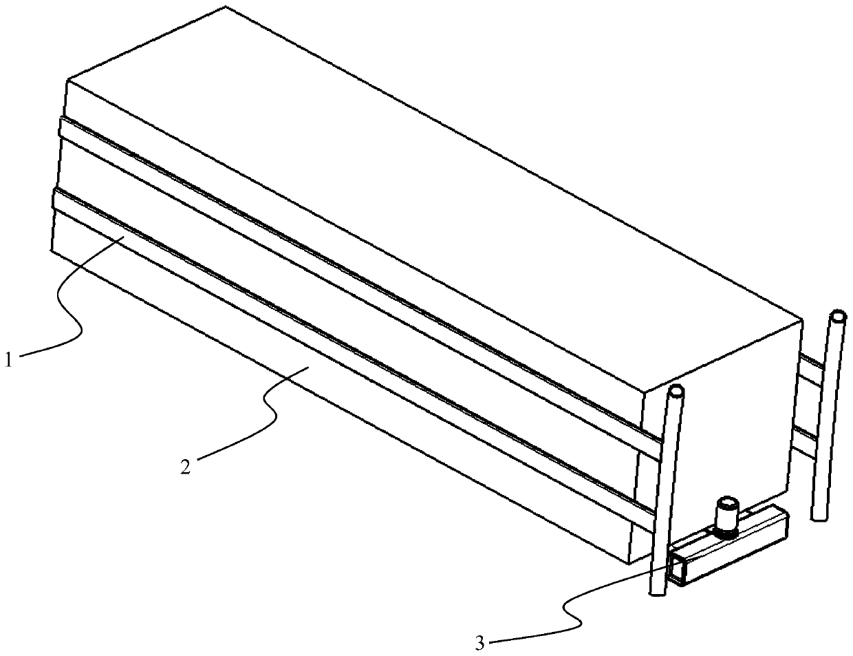
[0030] In this embodiment, the technical problem to be solved by the present invention is that the prior art uses a liquid-cooled plate, but when the liquid-cooled plate is installed on the side of the battery module, it needs to be fixed on the side, and the temperature of the coolant at the inlet section of the coolant is low, and the heat exchange effect Well, the coolant temperature at the coolant outlet section is high, the heat transfer effect is poor, and there is a temperature difference between the inlet and outlet water ends, and the use of a liquid cold plate will additionally increase the risk of leakage. A battery thermal management system based on heat pipes and liquid cooling devices is provided. A battery thermal management system based on heat pipes and liquid cooling devices includes:

[0031] A battery module 2, a cooling device and a control device, the control device and the cooling device communicate with each other through electrical signals, the cooling ...


PUM


Abstract

The invention discloses a battery thermal management system based on a heat pipe and a liquid cooling device. The battery thermal management system comprises a battery module, a cooling device and a control device, wherein the control device and the cooling device are communicated with each other through an electric signal, the cooling device is installed outside the battery module, the control device is electrically connected with the battery module, the cooling device comprises a heat pipe and a liquid cooling plate, the heat pipe and the liquid cooling plate are both mounted outside the battery module, the control device comprises an electric control device and a flow control device, the electric control device is electrically connected with the flow control device and the battery module, and the flow control device is communicated with the heat pipe and the liquid cooling plate through pipelines. According to the invention, the problem that temperature difference is prone to occurring due to uneven heat dissipation of the liquid cooling plate is solved, heat dissipation is even, and the size of the heat dissipation structure is reduced.

Description

technical field [0001] The invention relates to the field of automobile chassis safety, in particular to a battery heat management system based on a heat pipe and a liquid cooling device. Background technique [0002] With the development of new energy technology, new energy vehicles have more stringent requirements on the charging and discharging power of the battery system and the operating environment. The higher and higher charging and discharging power will cause the battery to generate heat. For local use, the test of the battery thermal management system is becoming more and more severe. [0003] However, the battery module cooling method mainly adopted by the existing thermal management system is to use a liquid cold plate to cool the battery module, mainly to arrange the liquid cold plate at the bottom and side of the module to cool the entire battery module. This cooling method mainly has the following problems: [0004] 1) If a liquid cold plate is used on the s...

Claims


Application Information

Patent Timeline
IPC IPC(8): H01M10/613H01M10/625H01M10/635H01M10/6552H01M10/6554H01M10/6567
CPCH01M10/613H01M10/625H01M10/635H01M10/6552H01M10/6554H01M10/6567Y02E60/10
Inventor 刘玮于林张鹏飞占莉潘福中
Owner GEELY AUTOMOBILE INST NINGBO CO LTD
Learn More