Eureka AIR delivers breakthrough ideas for toughest innovation challenges, trusted by R&D personnel around the world.

Broadband ventilation and sound insulation window unit structure and application thereof

A unit structure, sound insulation window technology, applied in door/window application, ventilation arrangement, sound insulation door/window, etc., can solve the problems of boundary refractive index mismatch, increase flow resistance, reduce ventilation effect, etc.

Pending Publication Date: 2020-08-21
TONGJI UNIV
View PDF10 Cites 8 Cited by
  • Summary
  • Abstract
  • Description
  • Claims
  • Application Information

AI Technical Summary

Problems solved by technology

However, the local resonance principle used by the former can only act at the resonance frequency, while the latter Fano resonance means that it only has narrow-band sound insulation near the single frequency point where interference occurs
However, metamaterials generally used for sound insulation only focus on the internal path design of sound waves, and the refractive index at the boundary of the structure does not match the air very much, so it can only achieve the effect of narrow-band sound insulation
Considering the fact that noise is usually broadband, designing a broadband noise barrier remains a great challenge
Although some studies have used multiple resonance methods to broaden the effective sound absorption frequency band, it still limits the bandwidth or reduces the ventilation effect to a certain extent.
In addition, traditional ventilation and sound insulation windows are usually composed of laying sound-absorbing materials or sound-absorbing structures in tortuous ventilation ducts, which increases flow resistance and is far less effective than direct ventilation paths

Method used


Image

  • Broadband ventilation and sound insulation window unit structure and application thereof
  • Broadband ventilation and sound insulation window unit structure and application thereof
  • Broadband ventilation and sound insulation window unit structure and application thereof

Examples


Embodiment Construction

[0034] The present invention will be described in detail below in conjunction with the accompanying drawings and specific embodiments. Apparently, the described embodiments are some, not all, embodiments of the present invention. Based on the embodiments of the present invention, all other embodiments obtained by persons of ordinary skill in the art without making creative efforts shall fall within the protection scope of the present invention.

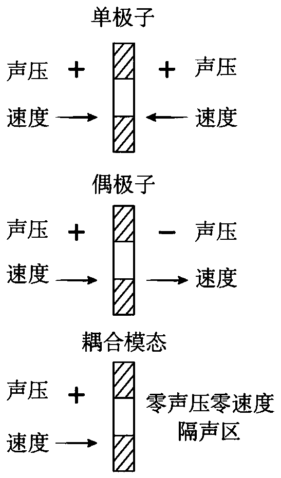
[0035]For the ventilation and sound insulation window unit with double structure, when it is regarded as a whole system, its surface response can be divided into monopole response and dipole response, and its coupling results can form the sound insulation effect. The present invention proposes a solution for homogenizing the ventilation barrier, which combines eigenmode analysis, that is, the transmission or reflection behavior of the sound barrier can be described by its eigenmode. The results show that the amplitude of transmitted ...


PUM


Abstract

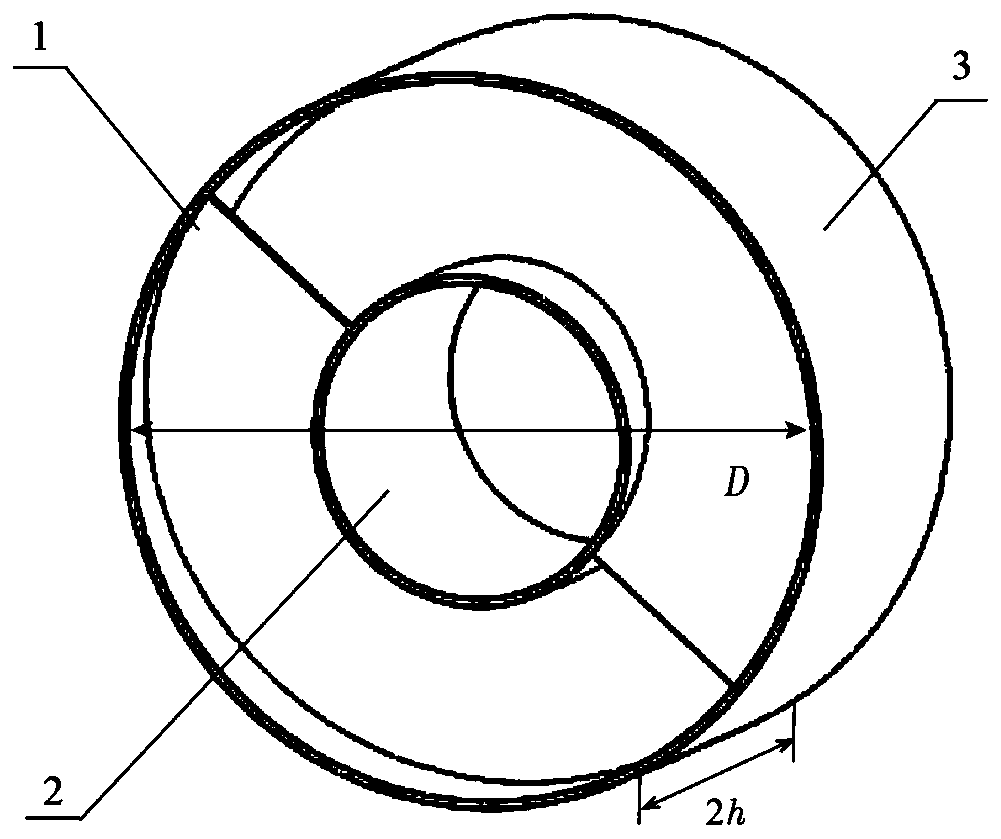
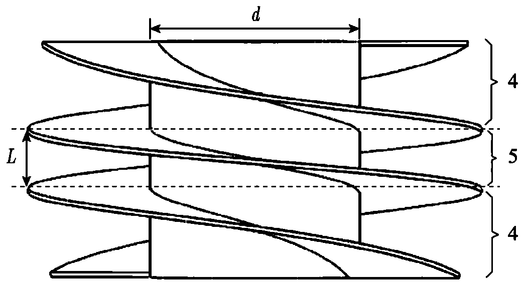
The invention relates to a broadband ventilation and sound insulation window unit structure and application thereof. The broadband ventilation and sound insulation window unit structure includes an inner spiral blade (1), a hollow tube (2) and a thin-walled shell (3); the outer wall of the hollow tube (2) is fixedly connected with the inner spiral blade (1); the thin-walled shell (3) is arranged at the outer edge of the inner spiral blade (1) in a covering manner; the inner spiral blade (1) includes a fixed spiral layer (5) and horn-shaped spiral layers (4), wherein the fixed spiral layer (5)is arranged around the center of the outer wall of the hollow tube (2), and the horn-shaped spiral layers (4) are mounted on two sides of the fixed spiral layer (5); a spiral blade of the fixed spirallayer (5) is a blade with a fixed pitch; and a spiral blade of each horn-shaped spiral layer (4) is a spiral blade with a gradient change in pitch. Compared with the prior art, the broadband ventilation and sound insulation window unit structure has the advantages that the sound insulation effect is improved, the application range is wide, and the like.

Description

technical field [0001] The invention relates to the technical field of noise control equipment, in particular to a broadband ventilation and sound insulation window unit structure and its application. Background technique [0002] Traditional sound barriers ignore air circulation while isolating noise, but there are still many special occasions that require ventilation in addition to noise reduction. For example, natural ventilation has become a key indicator in contemporary green buildings, but it will inevitably give Residents bring accompanying outside noise. In order to achieve the effect of ventilation and sound insulation, a common strategy is to install ventilation ducts with acoustic linings or perforated partitions. In practical applications, such ventilation ducts are generally designed as winding paths, but sufficient noise reduction is ensured. At the same time, it will bring a large pressure difference, which further reduces the ventilation effect. Therefore, ...

Claims


Application Information

Patent Timeline
Patent Type & Authority Applications(China)
IPC IPC(8): E06B5/20E06B7/02G10K11/16
CPCE06B5/205E06B7/02G10K11/161
Inventor 王旭李勇孙曼毛东兴
Owner TONGJI UNIV
Why Eureka
Eureka Blog
Learn More