Eureka AIR delivers breakthrough ideas for toughest innovation challenges, trusted by R&D personnel around the world.

A device for detecting steel structures using airflow feedback force

A technology of feedback force and steel structure, applied in metal processing equipment, grinding/polishing equipment, measuring devices, etc., can solve problems such as different grinding depths, easy rust on steel structures, and large detection errors

Active Publication Date: 2021-08-24
山东远腾环保设备有限公司
View PDF12 Cites 0 Cited by
  • Summary
  • Abstract
  • Description
  • Claims
  • Application Information

AI Technical Summary

Problems solved by technology

[0003] The existing steel plate crack detection method is light observation. Although light observation can detect cracks, it requires workers to concentrate on watching, and the steel structure after production is prone to rust, which sometimes covers some small cracks, so this The detection error of this method is relatively large; in addition, most of the existing derusting mechanisms are manually or extruded for grinding, no matter which grinding method will exert pressure on the steel structure, and different pressures will cause grinding Different depths affect the smoothness of the steel structure surface, so a device that uses airflow feedback force to detect steel structures came into being

Method used


Image

  • A device for detecting steel structures using airflow feedback force
  • A device for detecting steel structures using airflow feedback force
  • A device for detecting steel structures using airflow feedback force

Examples


Embodiment Construction

[0022] The following will clearly and completely describe the technical solutions in the embodiments of the present invention with reference to the accompanying drawings in the embodiments of the present invention. Obviously, the described embodiments are only some, not all, embodiments of the present invention. Based on the embodiments of the present invention, all other embodiments obtained by persons of ordinary skill in the art without making creative efforts belong to the protection scope of the present invention.

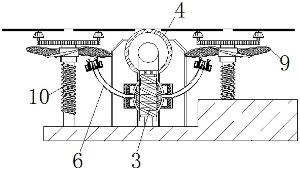
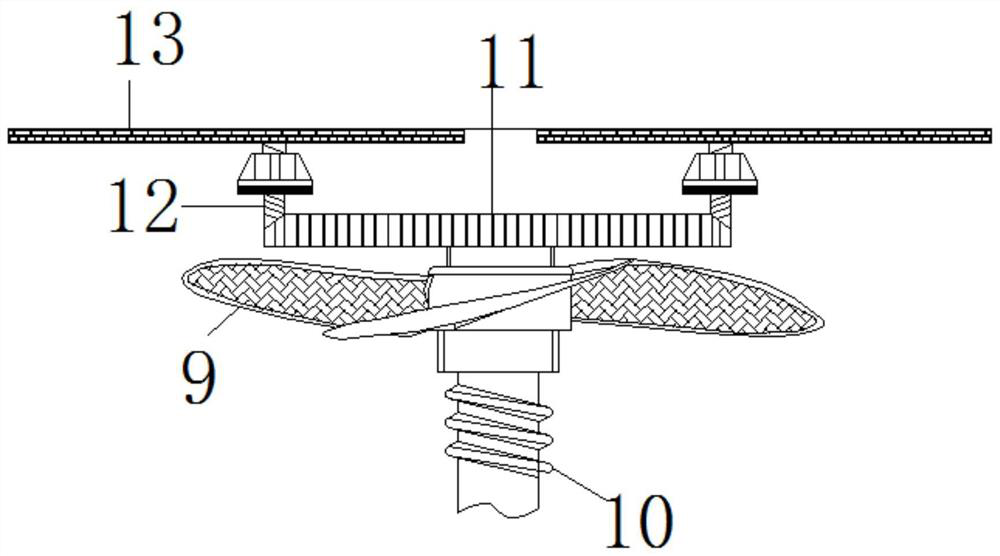
[0023] see Figure 1-6 , a steel structure detection device using airflow feedback force, comprising a base 1, the surface of the base 1 is fixedly connected with a support frame 2, the inside of the support frame 2 is movably connected with a spring rod 3, and the top of the spring rod 3 is movably connected with a roller 4. The roller 4 and the sand board 13 are not at the same height. The roller 4 is made of elastic rubber to prevent the surface of the poli...


PUM


Abstract

The invention relates to the technical field of steel structure detection, and discloses a steel structure detection equipment using airflow feedback force, including a base, the surface of the base is fixedly connected with a support frame, and the inside of the support frame is movably connected with a spring rod, a spring The top of the rod is movably connected with rollers, the two sides of the spring rod are slidably connected with squeeze plates, the surface of the squeeze plate is movably connected with an air supply pipe, and the end of the air supply pipe away from the squeeze plate is fixedly connected with an air guide box, and the surface of the air guide box is movable A fan blade is connected, the surface of the fan blade is movably connected with a rotating shaft, the top of the rotating shaft is movably connected with a worm wheel, the surface of the worm wheel is movably connected with a worm, and the surface of the worm is movably connected with a sand plate. Then the debris will be blown by the fan blades to move upwards, collide with the steel structure and scatter on the base. If there are cracks on the surface of the steel structure at this time, the debris will be blown into the cracks, so the use of grinding debris can be achieved. Drop conditions detect the effect of cracks on the steel plate surface.

Description

technical field [0001] The invention relates to the technical field of steel structure detection, in particular to steel structure detection equipment using airflow feedback force. Background technique [0002] Steel structure is a structure composed of steel materials, which is one of the main types of building structures. The structure is mainly composed of steel beams, steel columns, steel trusses and other components made of section steel and steel plates, and is made of rust and rust removal processes such as silanization, pure manganese phosphating, washing and drying, and galvanizing. The final steel structure needs to be tested for cracks to prevent unqualified steel plates from flowing into the market. [0003] The existing steel plate crack detection method is light observation. Although light observation can detect cracks, it requires workers to concentrate on watching, and the steel structure after production is prone to rust, which sometimes covers some small c...

Claims


Application Information

Patent Timeline
Patent Type & Authority Patents(China)
IPC IPC(8): B24B27/033B24B55/06B24B49/00G01N33/2045
CPCB24B27/033B24B49/00B24B55/06G01N33/2045
Inventor 李静雯李豪铭徐光海
Owner 山东远腾环保设备有限公司
Why Eureka
Eureka Blog
Learn More