Thin-film actuated reflection mirror having increased tilting angle

A thin-film mirror and mirror technology, which is applied in the field of optical projection systems, can solve the problems of the limited inclination angle of the thin-film actuated mirror 100 and the reduction of the overall optical efficiency of the thin-film actuated mirror.

Inactive Publication Date: 2003-07-23
DAEWOO ELECTRONICS CO LTD
View PDF0 Cites 0 Cited by
  • Summary
  • Abstract
  • Description
  • Claims
  • Application Information

AI Technical Summary

Problems solved by technology

The first thin-film electrode 185 of the thin-film actuated mirror 101 as a mirror is divided into an actuating part 220 and a reflective part 230 by a horizontal strip 187, and for an electric field applied thereto, only the actuating part 220 is def

Method used


Image

  • Thin-film actuated reflection mirror having increased tilting angle
  • Thin-film actuated reflection mirror having increased tilting angle
  • Thin-film actuated reflection mirror having increased tilting angle

Examples


Embodiment Construction

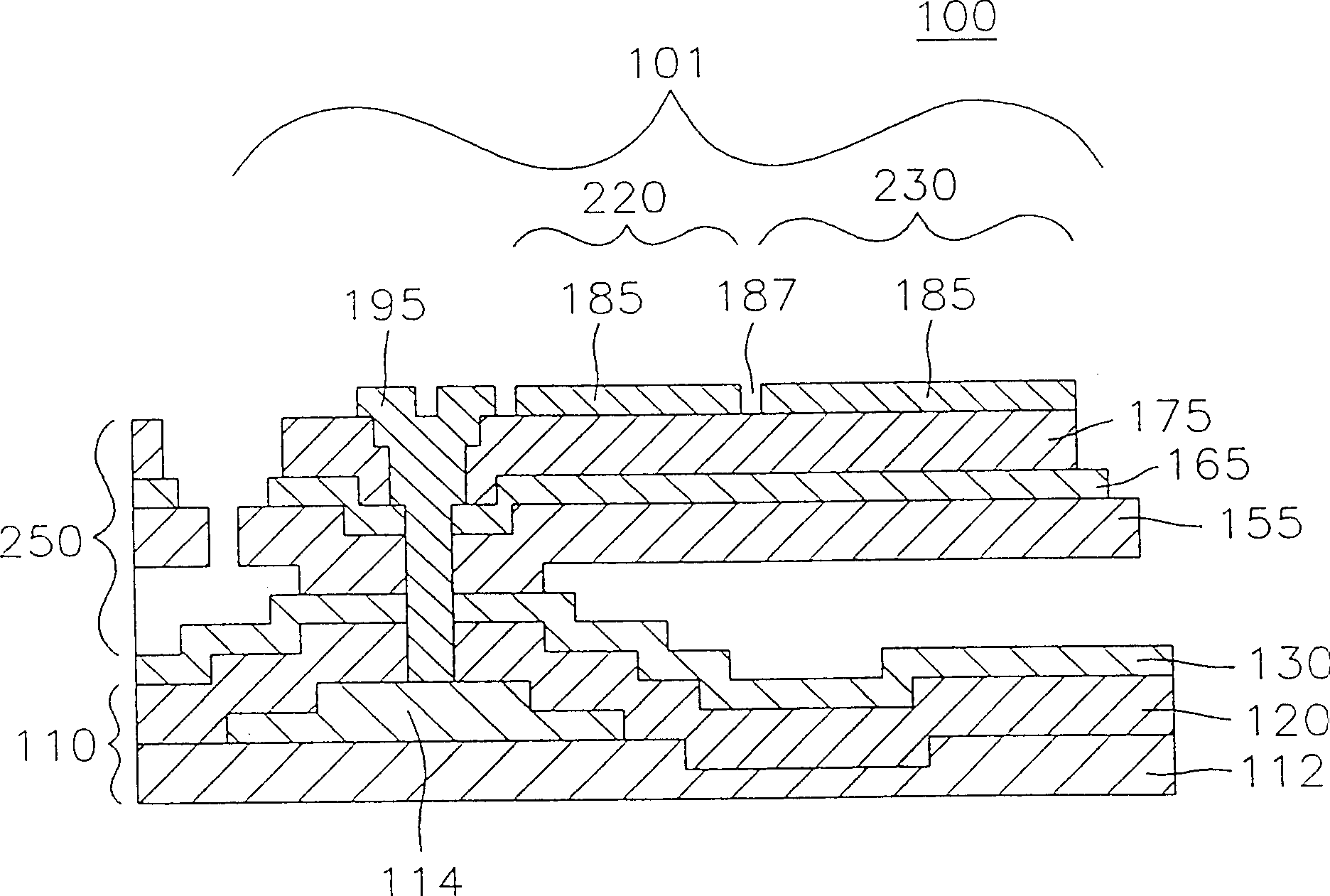
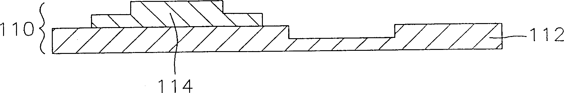
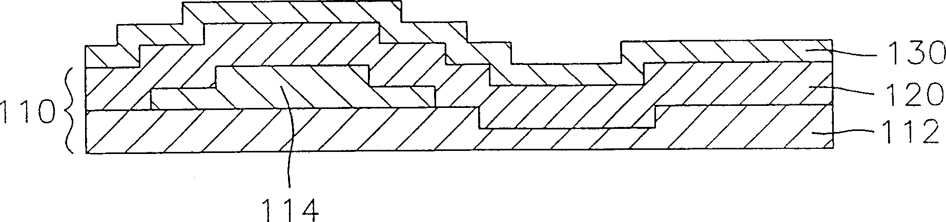
[0048] image 3 , 4A , 4B, 4C and Figures 5A-5M A cross-sectional view of an array 420 of M×N thin-film actuated mirrors 421 used in an optical projection system according to the present invention is respectively given, one along image 3 Schematic cross-sectional views of the array 300 of actuated mirrors 301 in line A-A and line B-B, one showing a cross-sectional view of a side actuator 430 of actuating mirror 301 and one showing a cross-sectional view of actuating mirror 301 A cross-sectional view of the central actuator 440 of , and a schematic cross-sectional view illustrating a method for fabricating an array 300 of M×N thin-film actuated mirrors 301 used in an optical projection system according to the present invention, where M and N is an integer. It should be noted that in image 3 , 4A , 4B, 4C and 5A-5M are denoted by like reference numerals.

[0049] Figure 4A In the figure, it is shown that the array 300 of the present invention includes an active matrix...


PUM


Abstract

An inventive array of M * N thin film actuated mirrors is provided with an active matrix, an array of actuating structures and an array of thin film mirrors, wherein the actuating structure is provided with a pair of side actuators and the center actuator, both ends of the side actuators being fixed to the active matrix, the upper thin film electrode of the side actuator electrically being connected to the lower thin film electrode of the center actuator to thereby function as a common bias electrode, the lower thin film electrode of the side actuator being connected to the upper thin film electrode of the center actuator to thereby function as a signal electrode. When the electric field is applied in the thin film actuated mirror, the side actuator expands and the center actuator contracts upward, allowing the thin film actuated mirror to tilt an increased angle.

Description

technical field [0001] The present invention relates to an optical projection system, and more particularly, to an array of M×N thin film actuated mirrors used in the system and a method of manufacturing the same, wherein each thin film actuated mirror can have a larger inclination. Background technique [0002] Among the various existing video display systems, known optical projection systems can provide large-scale high-quality displays. In such an optical projection system, light from a lamp is uniformly illuminated, for example, on an array of M x N actuated mirrors, where each mirror is connected to each actuator. These actuators may be made of electrodisplaceable materials capable of deforming in response to an electric field applied thereto, such as piezoelectric or electrostrictive materials. [0003] The reflected light beams from each mirror are incident on an aperture such as a diaphragm. By applying an electrical signal to each actuator, the relative position ...

Claims


Application Information

Patent Timeline
IPC IPC(8): G02F1/015G02B5/08G02B26/08H04N5/74
CPCG02B26/0858G02F1/015
Inventor 李华善
Owner DAEWOO ELECTRONICS CO LTD
Why Eureka
Try Eureka