Power-taking power system mounting structure in tractor

A technology of power system and installation structure, applied in the field of tractor, can solve the problem of easy to produce large inclination angle, etc., and achieve the effect of ensuring stability

Inactive Publication Date: 2019-10-22
WUHU CIMC RUIJIANG AUTOMOBILE
View PDF6 Cites 0 Cited by
  • Summary
  • Abstract
  • Description
  • Claims
  • Application Information

AI Technical Summary

Problems solved by technology

[0003] The purpose of the present invention is to provide an installation structure for the power take-off power system in the middle of the tractor, so as to solve the problem that the installation structure of the power take-off in the prior art tractor is prone to large inclination angles

Method used


Image

  • Power-taking power system mounting structure in tractor
  • Power-taking power system mounting structure in tractor

Examples


Embodiment Construction

[0012] The present invention will be further described below in conjunction with the accompanying drawings and embodiments.

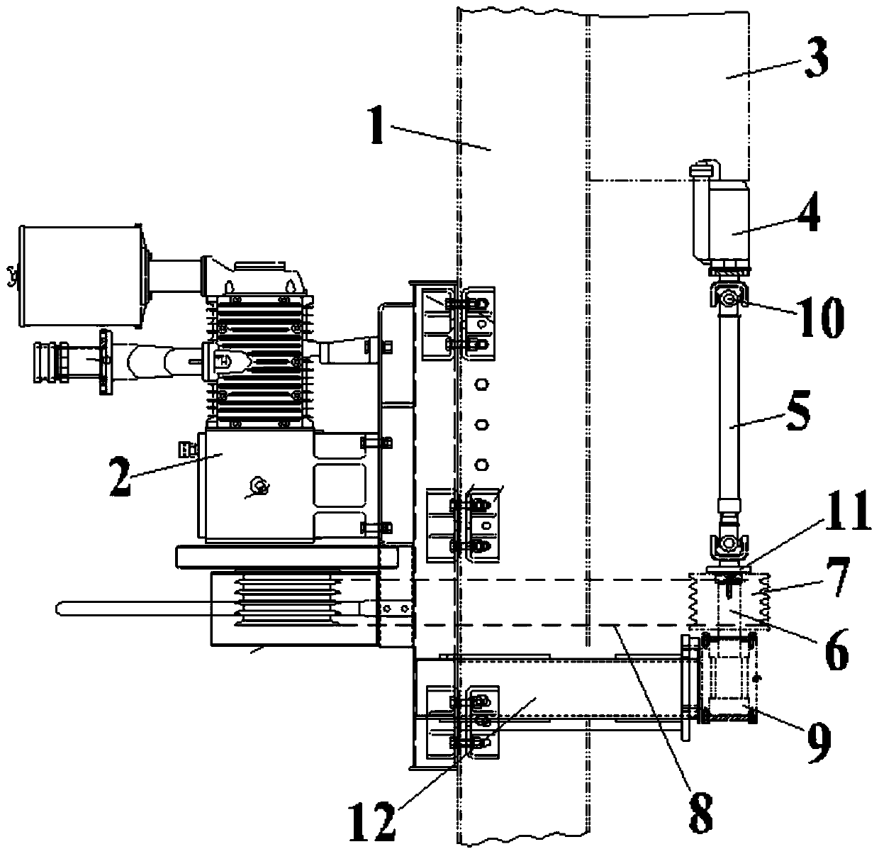
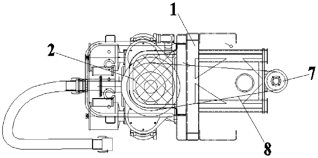
[0013] Such as figure 1 , figure 2 As shown, an installation structure of a power take-off power system in the middle of a tractor includes a frame assembly 1, an air compressor 2 is fixedly installed on one side of the frame assembly 1, and a gearbox 3 is installed on the upper part of the other side of the frame assembly 1, A power take-off 4 is provided below the gearbox 3, and the input shaft of the power take-off 4 is vertically connected to the gearbox 3. A main vehicle transmission shaft 5 is provided directly below the power take-off 4, and the upper end of the main vehicle transmission shaft 5 is the same as The shaft is connected to the output shaft of the power take-off 4, and the first shaft 6 is arranged directly below the transmission shaft 5 of the main vehicle. The upper end of the first shaft 6 is coaxially connected with the lower en...


PUM


Abstract

The invention discloses a power-taking power system mounting structure in a tractor. The power-taking power system mounting structure comprises a frame assembly, wherein one side of the frame assemblyis fixedly provided with an air compressor, the upper portion of the other side of the frame assembly is provided with a gearbox, the lower portion of the gearbox is sequentially in transmission connection with a power takeoff, a main vehicle transmission shaft and a first shaft, a belt wheel is coaxially and fixedly arranged on the first shaft, the belt wheel is in transmission connection with apower wheel of the air compressor through a triangular belt, a bearing is fixed at the position, located at the lower end of the first shaft, of the other side of the frame assembly, and the lower end of the first shaft is rotationally installed in the bearing. According to the power-taking power system mounting structure in the tractor, the power takeoff, the main vehicle transmission shaft andthe first shaft are integrally hoisted and connected from top to bottom so that a large inclination angle of the force takeoff relative to the horizontal plane can be avoided, and the stability of power transmission can be ensured.

Description

technical field [0001] The invention relates to the field of tractors, in particular to a tractor-mounted power-taking power system installation structure. Background technique [0002] In the conventional installation structure of the tractor, the power take-off is generally located directly below the drive shaft of the main vehicle, and it is easy to have a large inclination angle with the horizontal plane during installation, which will cause the drive shaft of the power take-off to fail to work normally. damage to the gearbox. Contents of the invention [0003] The purpose of the present invention is to provide an installation structure of the power take-off power system in the middle of the tractor, so as to solve the problem that the installation structure of the power take-off in the tractor in the prior art is easy to produce a large inclination angle. [0004] In order to achieve the above object, the technical scheme adopted in the present invention is: [0005...

Claims


Application Information

Patent Timeline
IPC IPC(8): B60K25/06
CPCB60K25/06
Inventor 张传运耿齐发吴松泉
Owner WUHU CIMC RUIJIANG AUTOMOBILE
Why Eureka
Try Eureka