Power conversion unit and mining frequency converter

A conversion unit and frequency converter technology, applied in the field of frequency converters, can solve the problems of increasing the difficulty of dismantling the faulty power conversion unit, difficult disassembly and assembly of the power conversion unit, prolonging the downtime of equipment failure, etc., achieving shortened downtime due to failure, improved performance, space-saving effect

Pending Publication Date: 2020-08-18
GUODIAN LONGYUAN ELECTRICAL +1
View PDF0 Cites 3 Cited by
  • Summary
  • Abstract
  • Description
  • Claims
  • Application Information

AI Technical Summary

Problems solved by technology

Due to the high voltage and large current at the external connection point of the power conversion unit, it is necessary to ensure a sufficient electrical safety distance and also consider the space limitation in the flameproof enclosure, resulting in complex structural design of the connection point and difficult insulation treatment.
The narrow space makes it inconvenient for workers to install in the flameproof enclosure, resulting in low production efficiency and increased failure rates
At the same time, the bolted connection method used at the connection point also increases the difficulty of dismantling the faulty power conversion unit, and the faulty equipment often needs to be lifted up to be repaired, which prolongs the downtime of the equipment
However, for the loads that operate continuously underground, there are strict assessment requirements for the downtime of equipment, and the power conversion unit that is not easy to disassemble cannot meet the needs of on-site maintenance of equipment, which is sometimes not allowed for continuous production coal enterprises

Method used


Image

  • Power conversion unit and mining frequency converter
  • Power conversion unit and mining frequency converter
  • Power conversion unit and mining frequency converter

Examples


Embodiment Construction

[0019] In order to enable those skilled in the art to better understand the technical solutions of the present disclosure, the present disclosure will be described in detail below in conjunction with the accompanying drawings and specific embodiments. Embodiments of the present disclosure will be described in further detail below in conjunction with the accompanying drawings and specific embodiments, but are not intended to limit the present disclosure.

[0020] Words such as "comprising" or "comprising" used in the present disclosure mean that the elements preceding the word cover the elements listed after the word, and the possibility of also covering other elements is not excluded. The technical term "unit" used in this disclosure is intended to represent a corresponding one of analog circuits, digital circuits, and program modules that realize corresponding functions. " application scenarios and the corresponding functions to be realized.

[0021] All terms (including tec...


PUM


Abstract

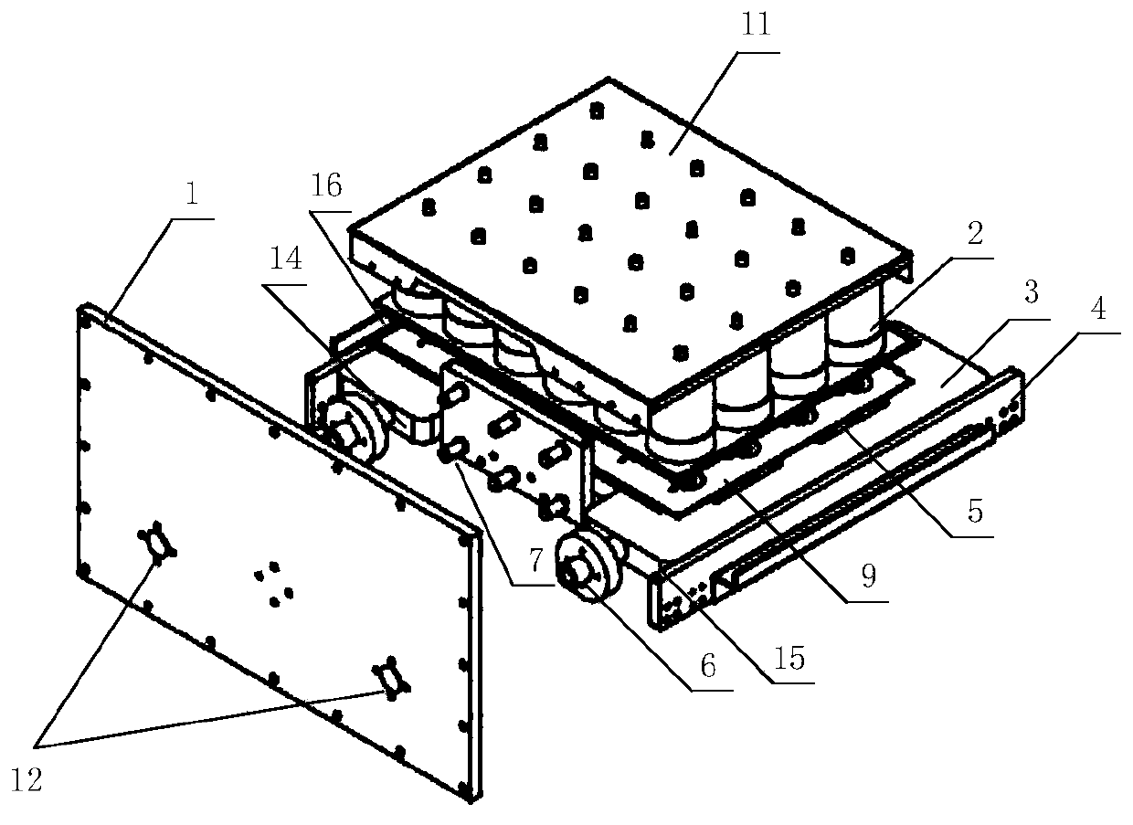
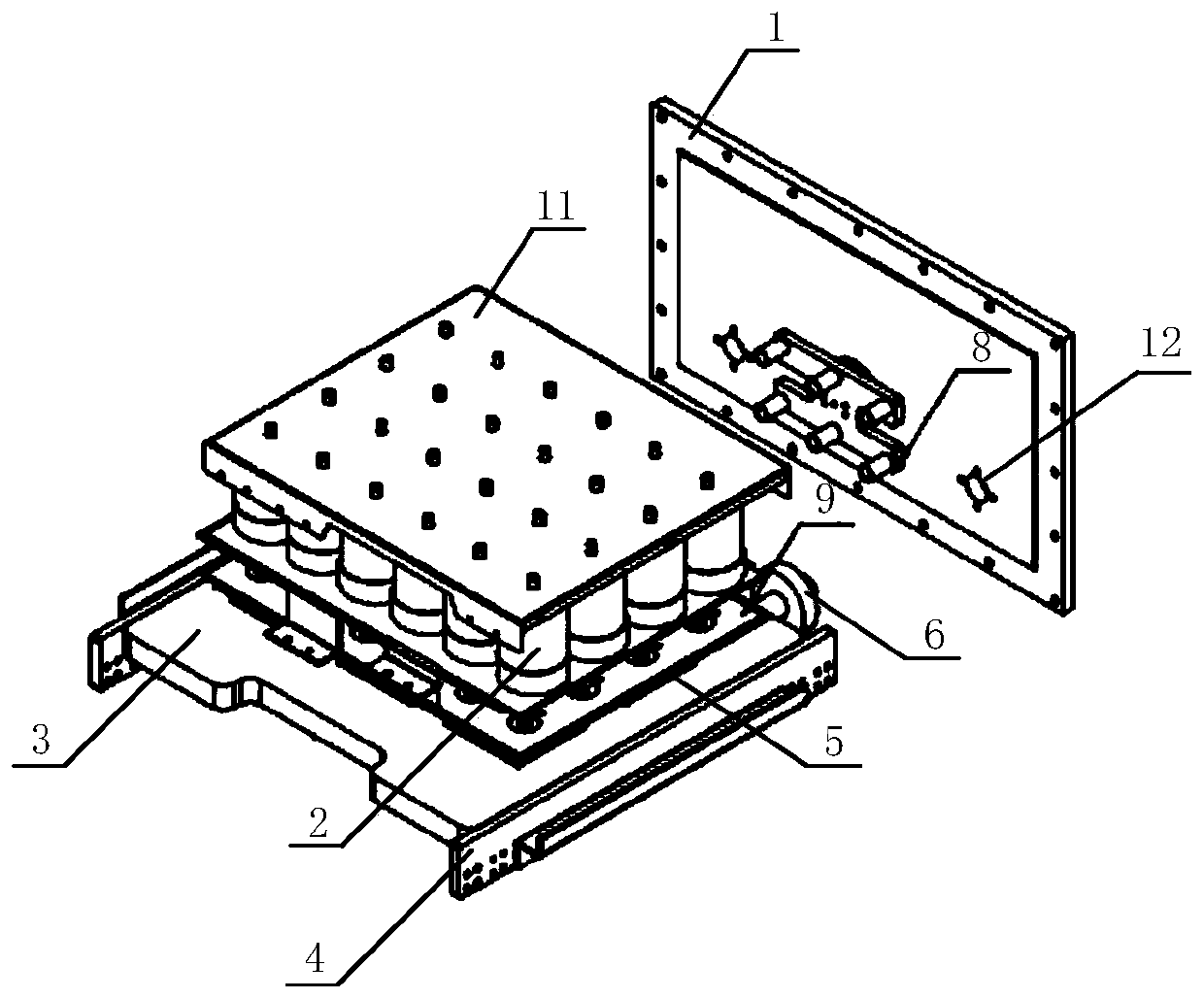
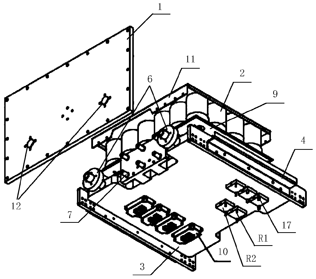
The invention provides a power conversion unit and a mining frequency converter. The power conversion unit is installed in a shell of the mining frequency converter. The power conversion unit comprises a water cooling plate; an inverter, a first DC bus system and a DC capacitor bank which are sequentially arranged on the first surface of the water cooling plate in a stacked mode; a second DC bus system which is arranged on the second surface of the water cooling plate; and a rectifier bridge which is electrically connected to the second DC bus system. The inverter is electrically connected with the DC capacitor bank through a first DC bus system; the first direct current bus system and the second direct current bus system are electrically connected. The power conversion unit further comprises a plug-in type connecting device, a plug part of the plug-in type connecting device is arranged on a first side surface of the water cooling plate, a socket part of the plug-in type connecting device is arranged on a rear plate of the shell, and slideways are respectively arranged on a second side surface and a third side surface of the water cooling plate. The power conversion unit can realize quick mounting and dismounting of a circuit system, improves the working efficiency, and can meet the requirements of equipment on-site maintenance.

Description

technical field [0001] The present disclosure relates to the field of frequency converters, and more specifically, to a power conversion unit and a mining frequency converter. Background technique [0002] At present, the water cooling plate of the mining frequency converter is usually fixed on the flameproof enclosure as a part of the rear cover of the flameproof enclosure. All components of the power conversion unit of the mining frequency converter are installed inside the water-cooled plate, that is, inside the flameproof enclosure, and the input and output ports of the power conversion unit and the peripheral circuits are connected by bolts. Due to the high voltage and large current at the external connection point of the power conversion unit, it is necessary to ensure a sufficient electrical safety distance and to consider the space limitation in the flameproof enclosure, resulting in complex structural design of the connection point and difficult insulation treatment...

Claims


Application Information

Patent Timeline
Patent Type & Authority Applications(China)
IPC IPC(8): H02M1/00H02M7/00H05K7/20
CPCH02M1/00H02M7/003H05K7/20927
Inventor 刘晓鹏李岩何亮朱峰曹晗罗雄飞张俊杰苏哲侃吕远侯丽楠梁弈
Owner GUODIAN LONGYUAN ELECTRICAL
Why Eureka
Try Eureka