Grinding and polishing fixture system and robot for aeroengine blade

A technology of aero-engine and fixture system, which is applied in the direction of grinding/polishing equipment, grinder, manipulator, etc. It can solve the problems of difficult blade processing and measurement, difficult programming, blade clamping and angle conversion, etc. Achieve the effects of improving practicability and scope of application, simplifying logic complexity, and improving equipment utilization

Active Publication Date: 2021-10-22
HUAZHONG UNIV OF SCI & TECH
View PDF7 Cites 0 Cited by
  • Summary
  • Abstract
  • Description
  • Claims
  • Application Information

AI Technical Summary

Problems solved by technology

The blades in the aero-engine are of various types, large in number and complex in shape, which makes the machining and measurement of the blades very difficult
[0003] Therefore, in order to solve the above-mentioned problems in the prior art, the applicant provides a blade processing equipment with strong environmental adaptability, high efficiency, and "measurement-processing" adaptive closed-loop processing capability. It measures while processing, and realizes blade measurement and processing. Integration, but because the robot needs to transfer the blade between different equipment (image acquisition device, grinding device, digital sample inspection machine, etc.), in order to adapt to the adjustment of the blade’s pose in different equipment, the robot must not only realize the automatic adjustment of the blade Pick and place, and at the same time switch the function of grabbing the angle of the blade, but the existing blade fixture can only realize one way of grabbing the blade. If switching is required, two robots need to be configured for cooperation, but the two robots It is very difficult to cooperate and cooperate, and it is easy to cause interference problems (such as the previous period of grinding has not ended, and the latter period of grinding has ended, or the previous period of grinding has been completed, and the latter period of grinding has not ended, resulting in two robots robbing the only one Grinding device and other unfavorable factors), so that the blade processing process cannot be carried out smoothly, and the programming is extremely difficult and complicated; at the same time, the setting of two robots leads to a large footprint of the equipment and a small space utilization rate, which is not conducive to batch production. Production and low competitiveness; the existing blade fixtures cannot realize blade clamping and angle conversion at all, and cannot meet the production needs of equipment. Therefore, the applicant has developed a grinding and polishing fixture system and robot that meet the above needs

Method used


Image

  • Grinding and polishing fixture system and robot for aeroengine blade
  • Grinding and polishing fixture system and robot for aeroengine blade
  • Grinding and polishing fixture system and robot for aeroengine blade

Examples


Embodiment Construction

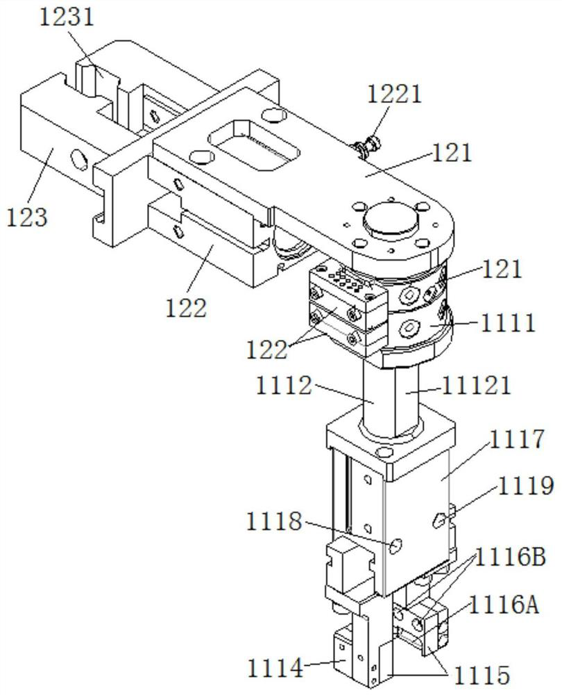
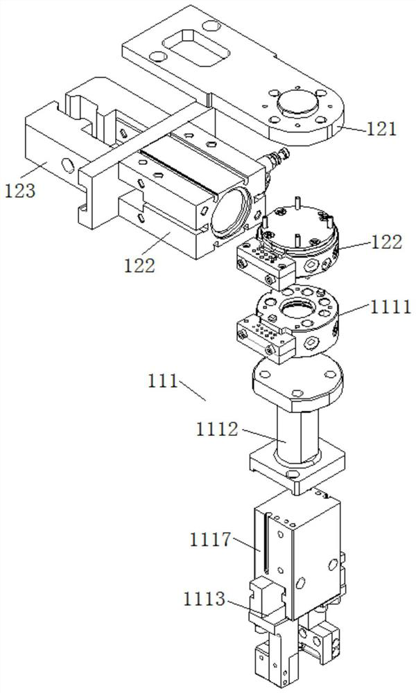
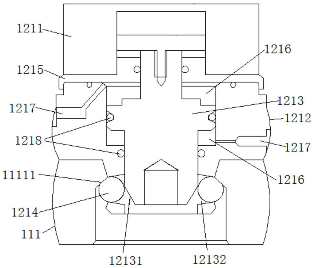
[0031] In order to make the object, technical solution and advantages of the present invention clearer, the present invention will be further described in detail below in conjunction with the accompanying drawings and embodiments. It should be understood that the specific embodiments described here are only used to explain the present invention, not to limit the present invention. In addition, the technical features involved in the various embodiments of the present invention described below can be combined with each other as long as they do not constitute a conflict with each other. For the convenience of description, it is described herein as an example that the male component is connected to the second grasping component and the female component is provided with a clamping member and a first grasping claw. Up, down, and left and right in this article refer to the left, right, left, and right of the drawings described, and do not fully represent the actual situation.

[003...


PUM


Abstract

The invention discloses an aeroengine blade grinding and polishing fixture system and a robot. The aeroengine blade grinding and polishing fixture system includes: a first grabbing assembly and a second grabbing assembly; the first grabbing assembly includes a matched male assembly and a female head assembly, the male head assembly and the female head assembly can be switched between a connected state and a disconnected state, one of the male head assembly and the female head assembly is connected to the second grabbing assembly, the male head assembly and the female head assembly The other one is provided with a first gripper for gripping the blade of an aero-engine and a gripper matched with the second gripper assembly; the gripper is connected with the first gripper, and the first gripper is far away from the second gripper Component settings. The invention effectively avoids the secondary clamping error caused by the blade being clamped by different components, ensures the intelligence of the equipment and the processing accuracy of mass production, and simultaneously ensures the stability, consistency and high yield of the finished blade quality.

Description

technical field [0001] The invention belongs to the technical field of aero-engine blade grinding and polishing, and more specifically relates to an aero-engine blade grinding and polishing fixture system and a robot. Background technique [0002] Aeroengine blades are the core components of aircraft power systems. Aeroengines rely on gas flow to generate thrust. Airflow enters from the air inlet, is compressed by the compressor, burns in the combustion chamber, expands through the turbine to perform work, and is discharged from the exhaust port to perform work in the airflow. During the process, the multi-stage blades in the compressor and turbine provide the main power output of the engine. The blades in aero-engines are of various types, large in number and complex in shape, which makes the machining and measurement of the blades very difficult. [0003] Therefore, in order to solve the above-mentioned problems in the prior art, the applicant provides a blade processing ...

Claims


Application Information

Patent Timeline
Patent Type & Authority Patents(China)
IPC IPC(8): B24B41/06B24B19/14B25J11/00
CPCB24B19/14B24B41/06B25J11/0065
Inventor 赵欢姜宗民丁汉
Owner HUAZHONG UNIV OF SCI & TECH
Why Eureka
Try Eureka