Machining process of aero-engine blade

A technology of aero-engine and processing technology, applied in metal processing equipment, metal processing machinery parts, manufacturing tools, etc., can solve the problems of low processing efficiency, prone to large deformation, scattered process distribution, etc., to facilitate clamping and positioning , Guarantee the effect of processing accuracy

Pending Publication Date: 2021-11-09
AECC AERO SCI & TECH CO LTD
View PDF9 Cites 0 Cited by
  • Summary
  • Abstract
  • Description
  • Claims
  • Application Information

AI Technical Summary

Problems solved by technology

[0006] The purpose of the present invention is to provide a processing technology for aero-engine blades, so as to solve the problems of cumbersome processing of existing aero-engine blades, scattered process distribution, frequent replacement of clamping fixtures, low processing accuracy and processing efficiency, and The problem of large deformation is prone to occur in the process of processing

Method used


Image

  • Machining process of aero-engine blade
  • Machining process of aero-engine blade
  • Machining process of aero-engine blade

Examples


Embodiment 1

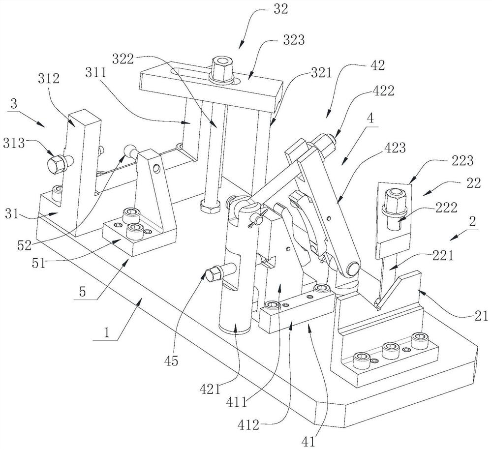
[0057] Please refer to image 3 with Figure 4 , the clamping device includes a base 1, a first pressing mechanism 2, a second pressing mechanism 3 and a supporting fastening mechanism 4, and the first pressing mechanism 2 and the second pressing mechanism 3 are longitudinally arranged at both ends of the base 1 respectively The supporting fastening mechanism 4 is arranged between the first pressing mechanism 2 and the second pressing mechanism 3 , and an axial positioning mechanism 5 is arranged between the first pressing mechanism 2 and the second pressing mechanism 3 . The blank includes a square process table, a mounting plate, a blade, a round table and a circular process table arranged in sequence. The first pressing mechanism 2 is used to clamp the round table or the circular craft table of the blank, the supporting fastening mechanism 4 is used to clamp the blade of the blank, and the second pressing mechanism 3 is used to clamp the mounting plate of the blank As wit...

Embodiment 2

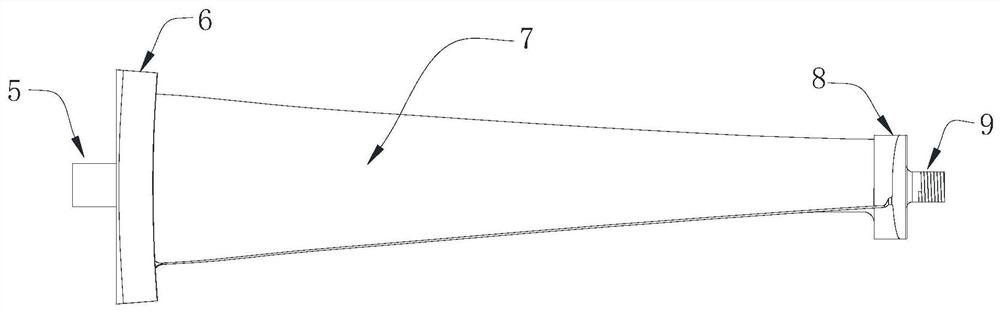
[0074] Please refer to figure 1 and figure 2 , a machining process for an aeroengine blade, comprising a blank, the blank comprising a square process table 53, a mounting plate 6, a blade 7, a round table 8, and an assembly shaft 9 arranged along the axial direction of the round table 8;

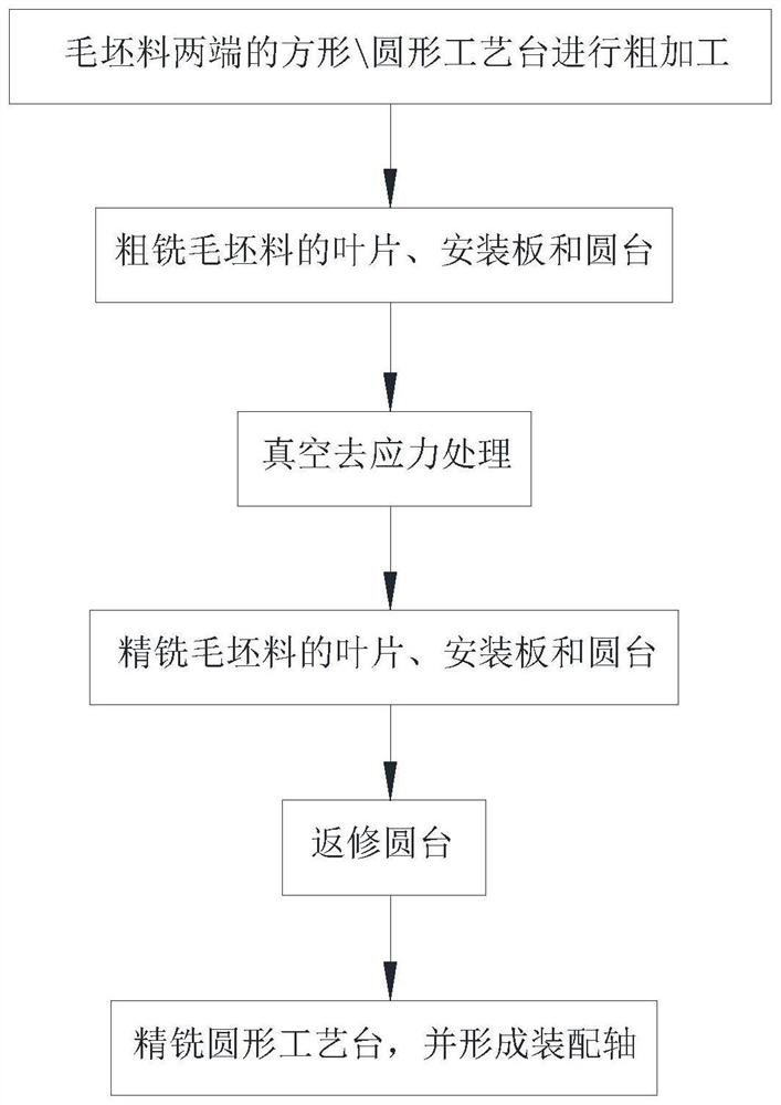
[0075] The processing technology based on above-mentioned raw material comprises the following steps:

[0076] S1: the blade 7 is clamped in the third compression chamber formed by the first floating support block 44 and the second floating support block 46, and the square process table 53 and the circular process table 9 are rough-machined on the machine tool; During the processing of the blank, a relatively accurate benchmark can be established, and at the same time, it is convenient to perform clamping operations on the square craft table 53 and the circular craft table 9;

[0077] S2: Place the square process table 53 in the second compression cavity formed by the U-shaped second comp...


PUM


Abstract

The invention discloses a machining process of an aero-engine blade, and particularly relates to the technical field of aero-engine blade precision machining. The machining process of the aero-engine blade comprises a blank material, and the blank material comprises a square process table, a mounting plate, the blade, a circular table and a circular process table which are sequentially arranged; the machining process comprises the following steps that S1, the blade is clamped, and rough machining is conducted on the square / circular process table; S2, the square / circular process table is clamped, and the mounting plate, the blade and the circular table are roughly milled; S3, the blank material is subjected to destressing treatment; S4, re-clamping is carried out, and finish machining is carried out on the mounting plate, the blade and the circular table; S5, the mounting plate and the blade are clamped, and the circular table is repaired; and S6, the circular table and the mounting plate are clamped, the circular process table is machined to form an assembly shaft, the square process table is milled off, and machining is completed. The machining process can effectively solve the problems that when the aero-engine blade is machined, large deformation occurs, and the machining quality and precision of the blade are reduced.

Description

technical field [0001] The invention relates to the technical field of precision machining of aeroengine blades, in particular to a processing technology of aeroengine blades. Background technique [0002] The aviation industry is compared to the crown of modern industry, and the aero-engine is even called the jewel in the crown of modern industry, which is the heart of the aircraft. During the use of aero-engines, blades are the key components of aero-generators, and the processing quality of aero-engine blades determines the performance level and service life of aero-engines. [0003] Aeroengine blades include turbine blades, compressor blades and fan blades. Fan blades are generally made of titanium alloy or aluminum alloy. The traditional processing route of this type of blade is to process the blade after both ends of the blade are processed. When cutting the blade, it is easy to damage the blade structure, and it will also affect the structure of both ends of the proc...

Claims


Application Information

Patent Timeline
IPC IPC(8): B23C3/00B23Q3/00
CPCB23C3/00B23Q3/00
Inventor 周晓伟唐波曾有鑫邓杰王宗彦李文平王艳春裴聪王晓莹王勇
Owner AECC AERO SCI & TECH CO LTD
Why Eureka
Try Eureka