Primary pulp dilution device for antibacterial fabric

A dilution device and technology for antibacterial fabrics, which is applied in the field of puree dilution devices for antibacterial fabrics, can solve problems such as substandard concentration, uneven distribution, and reduced dilution efficiency, and achieve uniform concentration, improve discharge efficiency, and increase dilution efficiency. Effect

Inactive Publication Date: 2020-08-18
合肥克拉伦斯科技有限公司
View PDF7 Cites 1 Cited by
  • Summary
  • Abstract
  • Description
  • Claims
  • Application Information

AI Technical Summary

Problems solved by technology

[0003] During the production and processing of antibacterial fabrics, various raw material slurries, that is, raw pulp, are needed. During the production process, the concentration of raw pulp is prone to fail to meet the standard, and the concentration of the raw pulp needs to be diluted to meet the standard. The applicant developed a This kind of puree dilution device, when diluting, the diluent is distributed unevenly when feeding, resulting in a decrease in the overall dilution efficiency and affecting the overall production efficiency

Method used


Image

  • Primary pulp dilution device for antibacterial fabric
  • Primary pulp dilution device for antibacterial fabric
  • Primary pulp dilution device for antibacterial fabric

Examples


Embodiment 1

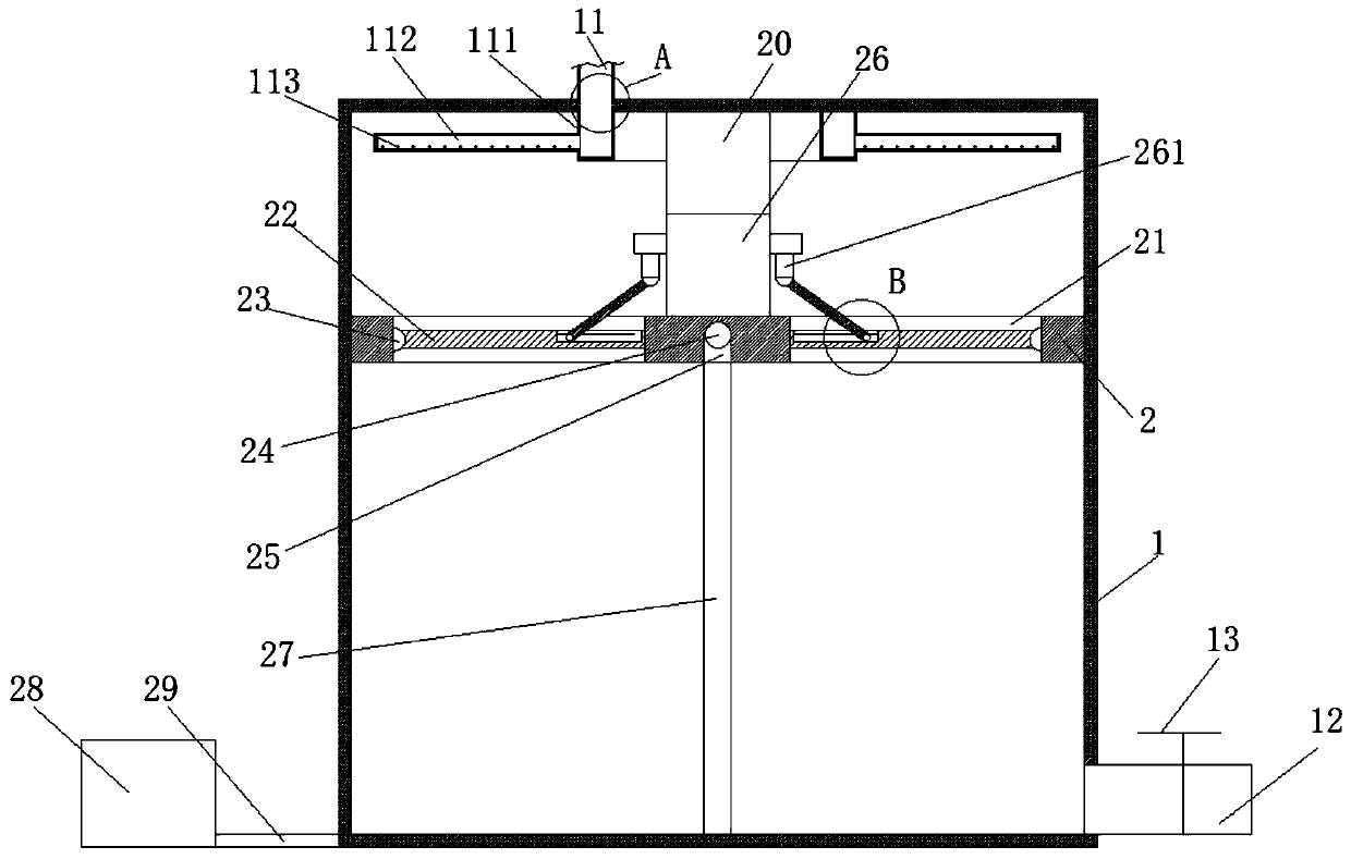
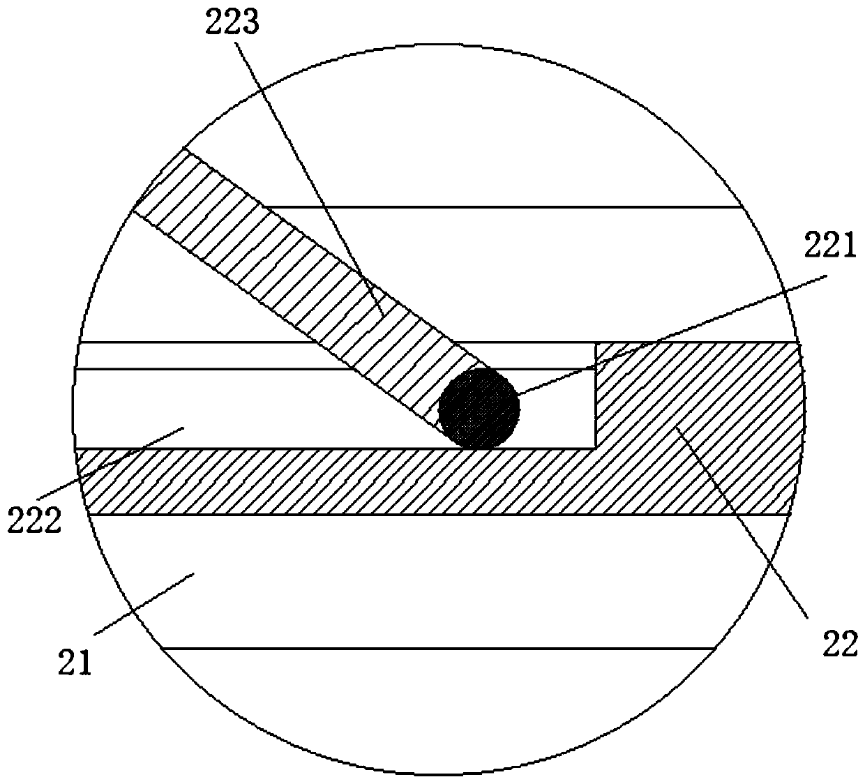
[0032] see Figure 1-3 , a puree dilution device for antibacterial fabrics, comprising a puree tank 1, the upper end of the puree tank 1 is provided with a feed pipe 11 for feeding, and one side of the bottom of the puree tank 1 is provided with a discharge port for discharging Pipe 12, and the dilution plate 2 that matches with the original slurry tank 1 and can slide up and down is provided in the original slurry tank 1, and the dilution plate 2 is provided with a plurality of through-type dilution tanks 21, and the inside of the dilution tank 21 A sealing cover 22 that can be opened and closed and used to seal the dilution tank 21 is provided. The bottom of the dilution pan 2 is provided with a communication hole 25 for the up and down communication of the dilution pan 2. The upper end of the dilution pan 2 is provided with a plurality of evenly distributed exposure holes. The air pipe 24, the aeration pipe 24 is provided with evenly distributed aeration holes 241, and the ...

Embodiment 2

[0038] The same as embodiment 1 is not repeated, and the difference with embodiment 1 is:

[0039] see Figure 4-5, the material distribution box 111 is an annular groove with an open upper end, and the inner wall of the puree tank 1 located at the upper end of the material distribution box 111 is provided with a material matching with the material distribution box 111 and sliding with the material distribution box 111 Connected distribution trough 116, the inner side walls of the distribution chute 116 are provided with an annular clamping groove 115, the clamping groove 115 is provided with a clamping plate 114 that matches the clamping groove 115 and is slidingly connected. The inner wall of the clamping plate 114 is fixedly connected with the corresponding outer wall of the distribution box 111 .

[0040] Further, the distributing pipe 112 is symmetrically distributed on the outside of the distributing box 111 with the distributing box 111 as the center, and the distribut...

Embodiment 3

[0043] The same as embodiment 1 is not repeated, and the difference with embodiment 1 is:

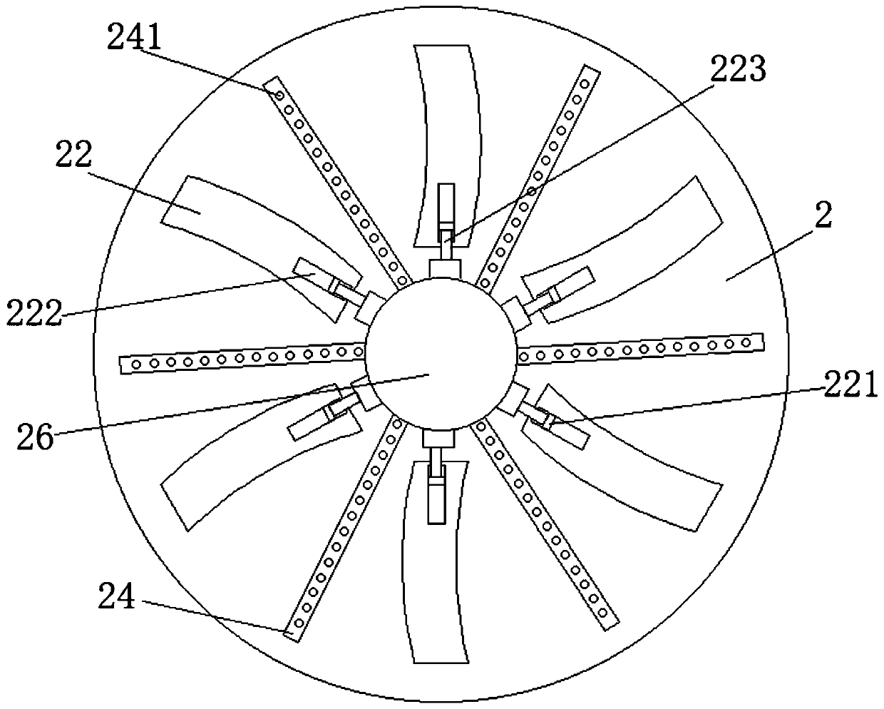
[0044] see Figure 6-7 , the dilution tanks 21 are distributed centrally symmetrically with the center of the dilution plate 2 as the center, and the two sides of the dilution tanks 21 are arc-shaped, and the dilution tanks 21 are distributed on the dilution plate 2 in the shape of fan blades.

[0045] Further, the cross-sections of the two side surfaces of the dilution tank 21 are inclined, one side of the dilution tank 21 is provided with a first fixing groove 211 for fixing one side of the sealing cover 22, and the other side of the dilution tank 21 is provided with a sealing cover for sealing. 22 and the second fixing groove 212 fixed on the other side, the depth of the first fixing groove 211 is smaller than the depth of the second fixing groove 212, and the bottom of the sealing cover 22 is inclined.

[0046] The unique design of the dilution tank 21, coupled with the flexible co...


PUM


Abstract

The invention belongs to the technical field of fabric raw stock dilution, in particular to a primary pulp dilution device for antibacterial fabric. A primary pulp tank is included, wherein a feedingpipe is arranged at the upper end of the primary pulp tank; a discharge pipe is arranged on one side of the bottom of the primary pulp tank; a diluting disc which is matched with the primary pulp tankand can slide up and down is arranged in the primary pulp tank; a plurality of through dilution grooves are formed in the dilution disc; a sealing cover which can be opened and closed and is used forsealing the dilution tank is arranged in the dilution tank; a communicating hole for communicating the diluting disc up and down is formed in the bottom of the diluting disc; a plurality of aerationpipes which are uniformly distributed are arranged at the upper end of the dilution disc; aeration holes which are uniformly distributed are formed in the aeration pipe; a movably connected material distribution box is arranged in the primary pulp tank, a plurality of communicated material distribution pipes are arranged on the outer side of the material distribution box, a plurality of material distribution holes are formed in the material distribution pipes, and the material distribution holes are uniformly distributed on the same side of the material distribution pipes in a line shape, so that diluent can be uniformly distributed in the primary pulp tank, and the overall dilution efficiency is improved.

Description

technical field [0001] The invention belongs to the technical field of puree dilution for fabrics, and in particular relates to a puree dilution device for antibacterial fabrics. Background technique [0002] Antibacterial fabric has good safety, it can effectively and completely remove bacteria, fungus and mildew on the fabric, keep the fabric clean, and prevent bacteria from regenerating and multiplying. [0003] During the production and processing of antibacterial fabrics, various raw material slurries, that is, raw pulp, are needed. During the production process, the concentration of raw pulp is prone to fail to meet the standard, and the concentration of the raw pulp needs to be diluted to meet the standard. The applicant developed a In the original slurry dilution device, when diluting, the diluent is unevenly distributed when feeding, which leads to a decrease in the overall dilution efficiency and affects the overall production efficiency. Contents of the inventio...

Claims


Application Information

Patent Timeline
IPC IPC(8): B01F7/26B01F13/02B01F15/00D06B23/20B01F27/93B01F33/40
CPCD06B23/205B01F27/93B01F33/4094B01F35/32015
Inventor 任礼新
Owner 合肥克拉伦斯科技有限公司
Why Eureka
Try Eureka