High-efficiency multifunctional motor

A multifunctional and efficient technology, applied in the direction of manufacturing motor generators, electromechanical devices, electrical components, etc., can solve the problems of reducing the efficiency of R&D product testing, increasing structural complexity, difficulty in winding, and not adapting to development requirements, etc., to achieve increased Effective performance, improved operability, and reduced winding difficulty

Pending Publication Date: 2020-08-14
天紫虹阳(唐山)电机有限公司
View PDF0 Cites 0 Cited by
  • Summary
  • Abstract
  • Description
  • Claims
  • Application Information

AI Technical Summary

Problems solved by technology

However, the existing motors are distributed winding and concentrated winding separately, and although the existing motors have a double-rotor mode, generally one rotor moves under the magnetic field, while the other rotor moves according to the shaft coupling. The relative rotation of the device, or increase the magnetic governor
The existing motor redundancy is based on one mode of winding redundancy, which is not suitable for all occasions, has no selectivity, low compatibility, increases the difficulty of research and development, reduces the efficiency of product testing, and has a complex structure , low maneuverability
Moreover, in the existing motors, distributed winding requires the existence of pole shoes, which increases the complexity of the structure and the difficulty of winding, and is increasingly unsuitable for development requirements.

Method used


Image

  • High-efficiency multifunctional motor
  • High-efficiency multifunctional motor
  • High-efficiency multifunctional motor

Examples


Embodiment Construction

[0033] The present invention will be further described in detail below in conjunction with the accompanying drawings and embodiments.

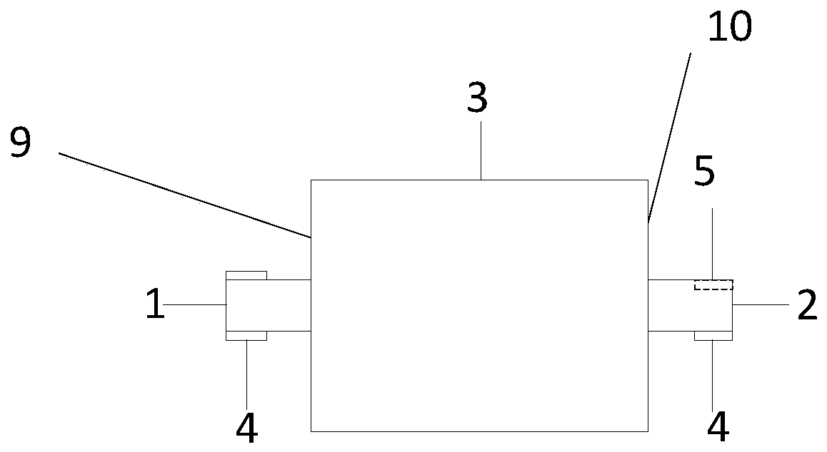
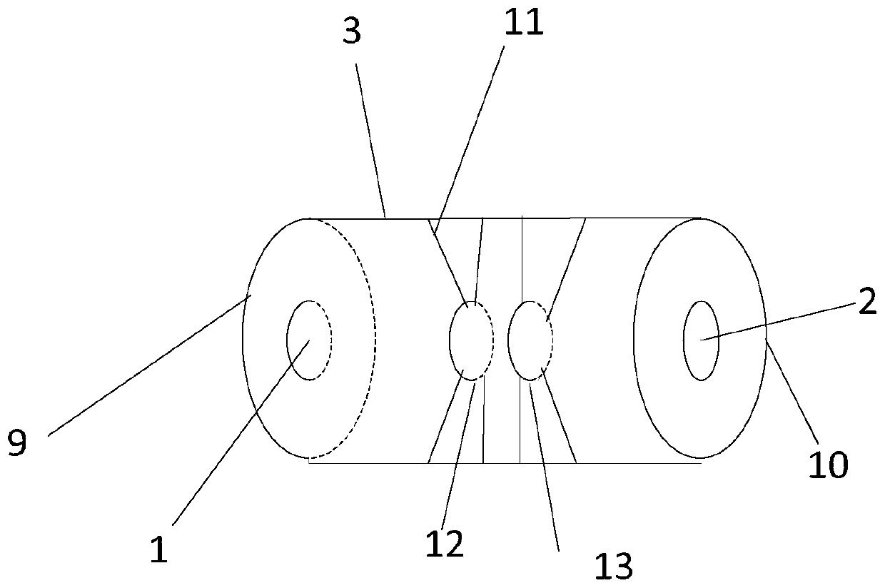
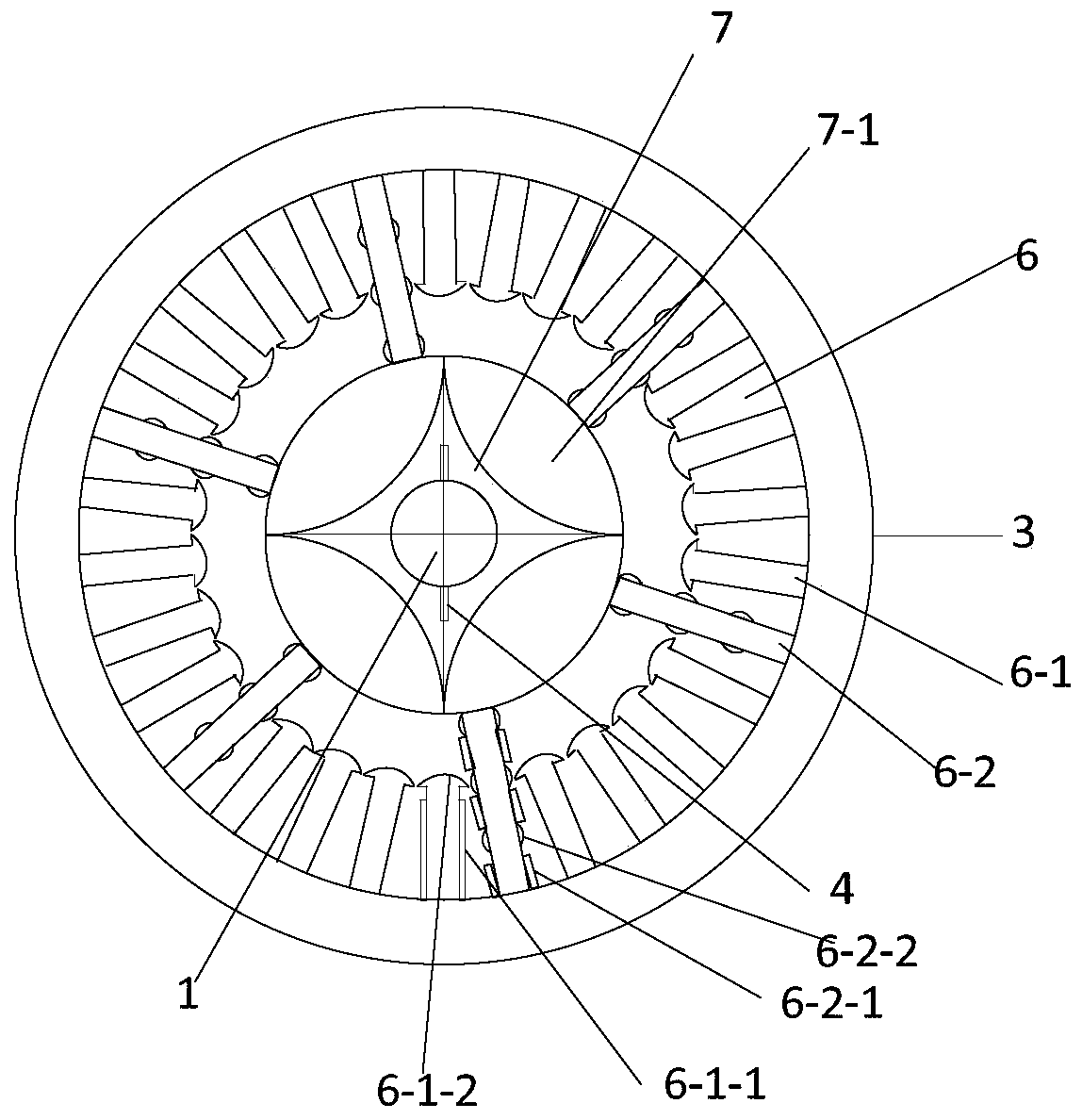
[0034] A high-efficiency multifunctional motor, such as Figure 1-2 As shown, it includes the first motor shaft 1, the second motor shaft 2, the motor casing 3, the shaft protrusion 4, the shaft notch 5, the motor stator 6, the first motor rotor 7, the second motor rotor 8, the first motor shaft The side cover 9 , the second motor shaft side cover 10 , the fixing steel wire 11 , the first shaft fixing slot 12 and the second shaft fixing slot 13 . The first motor shaft 1 and the second motor shaft 2 are used to connect with other equipment, which ensures that the torque and speed of the motor can be transmitted to other equipment.

[0035] Such as Figure 1-4 As shown, the first motor shaft 1 is connected to the shaft protrusion 4; at the same time, it is connected to the first motor rotor 7; the second motor shaft 2 is connected to the shaft...


PUM


Abstract

The invention relates to the technical field of motors, in particular to a high-efficiency multifunctional motor. The motor comprises a first motor rotating shaft, a second motor rotating shaft, a motor shell, a motor stator, a first motor rotor, a second motor rotor, a first motor rotating shaft side outer cover, a second motor rotating shaft side outer cover, a fixing steel wire, a first rotating shaft fixing groove and a second rotating shaft fixing groove. The motor can be suitable for different states according to different application occasions, application requirements, performance andfunction requirements, the stability of the motor is improved, the adaptive capacity of the motor is ensured, and the size of the motor is reduced; a pole shoe mode is abandoned, the structure is simplified, and the winding is facilitated. According to the invention, a plurality of working modes are integrated, different working occasions can be used in each mode, the operation is convenient, thepracticability of the motor is improved, the functions of the motor are increased, and the utilization rate of the motor is ensured.

Description

technical field [0001] The invention relates to the technical field of motors, in particular to a high-efficiency multifunctional motor. Background technique [0002] A motor is an electromagnetic device that converts or transmits electrical energy according to the law of electromagnetic induction, or converts one form of electrical energy into another form of electrical energy. Motors are generally composed of important components such as stators, rotors, magnets, and rotating shafts. According to different winding forms, they are divided into two types of motors: distributed winding motors and concentrated winding motors. [0003] The motor is mainly to provide power and speed to the equipment. With the development of intelligent technology, motors are used almost everywhere that can be moved, and different occasions have different requirements for the performance of the motor, and the structure of the motor is also different; as the compatibility becomes higher and highe...

Claims


Application Information

Patent Timeline
IPC IPC(8): H02K5/04H02K1/27H02K5/18H02K3/28H02K16/02H02K1/16H02K3/46H02K3/12H02K5/10H02K7/00H02K15/00
CPCH02K1/165H02K1/276H02K3/12H02K3/28H02K3/46H02K5/04H02K5/10H02K5/18H02K7/003H02K15/00H02K16/02
Inventor 董立军
Owner 天紫虹阳(唐山)电机有限公司
Why Eureka
Try Eureka