
Process route modeling method and system for manufacturing execution system

A technology of manufacturing execution system and process route, which is applied in the field of vehicles, can solve problems such as low circulation efficiency and process route solidification, and achieve the effect of simple and complete process route

Active Publication Date: 2020-08-14
SHANGHAI SMARTSTATE TECH CO LTD
View PDF4 Cites 3 Cited by
  • Summary
  • Abstract
  • Description
  • Claims
  • Application Information

AI Technical Summary

Problems solved by technology

[0005] Aiming at the deficiencies of the existing technology, the present invention solves the problems of solidified process routes and low circulation efficiency in the traditional manufacturing execution system, and realizes that the manufacturing execution system can flexibly manage and control the production line and schedule tasks

Method used


Image

  • Process route modeling method and system for manufacturing execution system
  • Process route modeling method and system for manufacturing execution system
  • Process route modeling method and system for manufacturing execution system

Examples


Embodiment 2

[0157] Embodiment 2 is a modification of embodiment 1

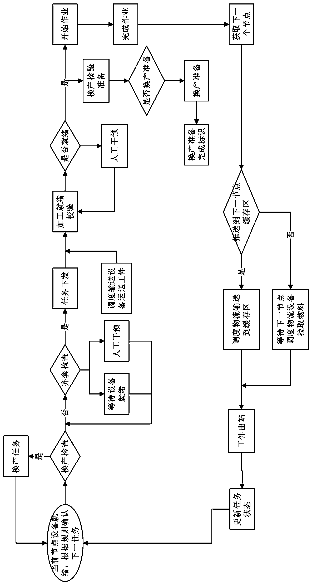
[0158] For the production queue of the manufacturing execution system of the flexible replacement production line, the production sequence is constructed in the form of dynamic reconstruction to improve production efficiency. like Figure 5 as shown,

[0159] Further, the basic approach is that there are several production sequences in the control system of the entire production line, and there are different parts A, B, etc. in these production sequences.

[0160] Furthermore, when A is processed and then B is processed, we need to change the production process formula slightly. If it is artificially replaced, it may not be possible for the heavy fixtures to be humanly accessible. We need AGV to carry the fixtures and other preparations for production change.

[0161] Furthermore, if you just wait for the processing of product A to be completed, and then issue a production replacement preparation command in the manageme...

Embodiment 3

[0167] Embodiment 3 is a variation of embodiment 1

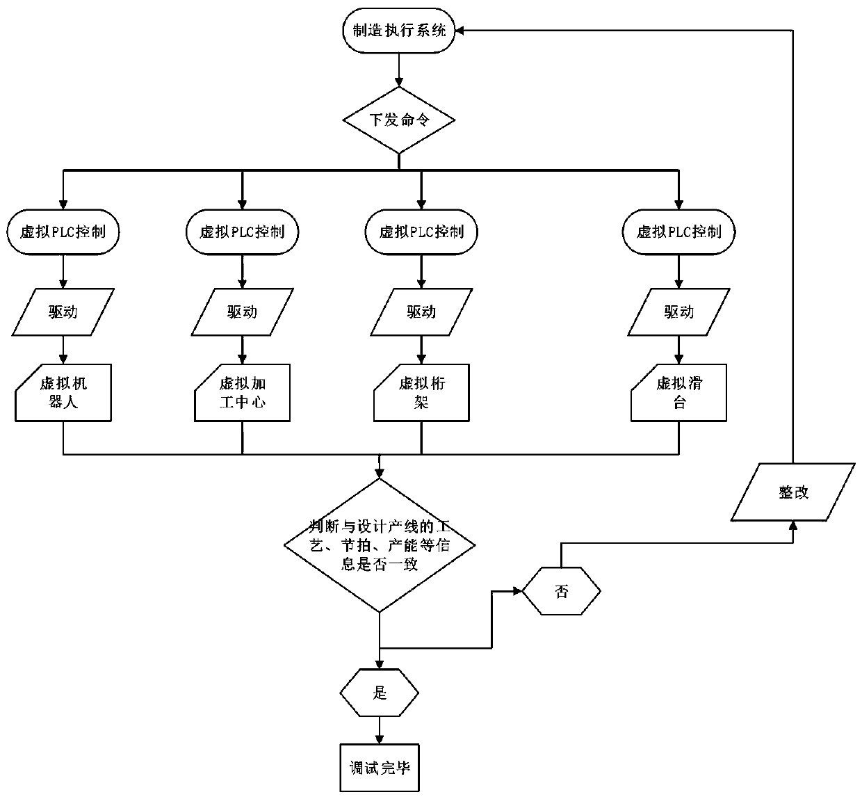
[0168] Embodiment 3 discloses a virtual commissioning method integrated with manufacturing execution system and production line, see image 3 As shown, the method includes:

[0169] Step N01: Judging whether the control result of the virtual PLC program is the same as that of the real PLC program, see Figure 4 shown;

[0170] Step N02: Use the written virtual PLC program to control the operation of the virtual production line. If the production capacity, tempo and process information of the virtual production line are the same as those of the designed production line, it means that the control results of the virtual PLC program and the real PLC program are the same ;

[0171] Step N03: If the production capacity, tempo and process information of the virtual production line under the control of the manufacturing execution system are different from the designed production line, then gradually modify the virtual PLC program...


PUM


Abstract

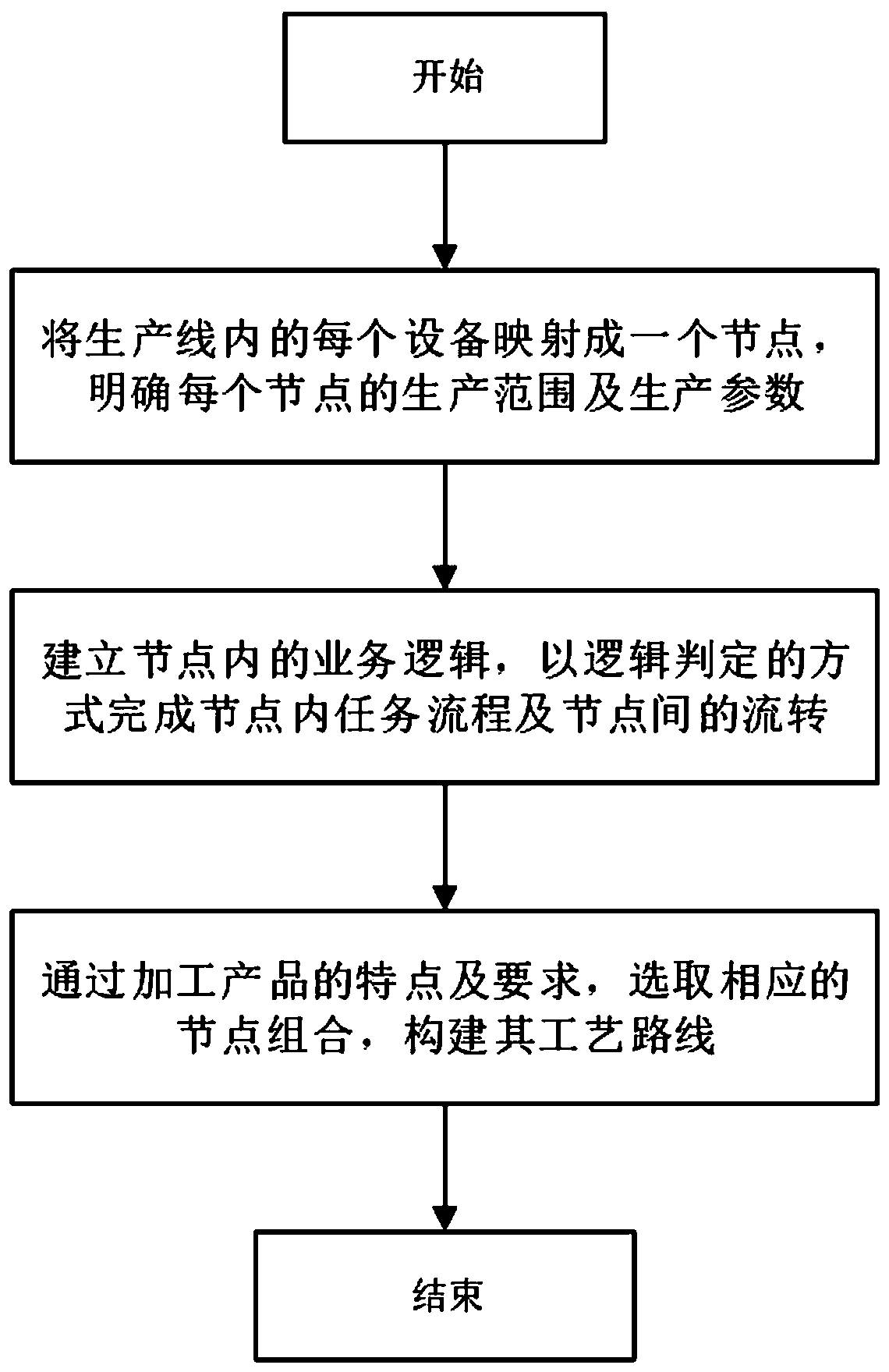
The invention provides a process route modeling method and system for a manufacturing execution system. The method comprises the steps of enabling each piece of equipment in a production line to be mapped into a node, determining the production range and production parameters of each node, and guaranteeing that the equipment is used in a specific parameter range; establishing service logic in thenodes, and completing task flows in the nodes and circulation among the nodes in a logic judgment mode; according to the characteristics and requirements of processed products, selecting correspondingnode combinations , and constructing a process route. According to the method for flexibly constructing the process route, the nodes serve as the minimum units in the process route, circulation between the nodes is completed in a judgment mode, the problem that the process route of a traditional manufacturing execution system is solidified, and the circulation efficiency is low is solved, and themanufacturing execution system can flexibly manage, control and schedule tasks on the production line.

Description

technical field [0001] The present invention relates to the field of vehicle technology, in particular, to a method and system for modeling a process route of a manufacturing execution system, and more specifically, to a method and system for modeling a process route of a manufacturing execution system for vehicle components. Background technique [0002] With the development of information technology and the deepening of the implementation of manufacturing information engineering, the traditional modeling method generates a single, rigid process route, which fails to effectively consider the construction of different production routes for different products and other tasks during production. Occupancy, production replacement tasks and other dynamic situations cause processing to wait or even stop processing, making the process route have to be re-modified or some resources are reused while some resources are rarely used, resulting in low efficiency. [0003] The invention d...

Claims


Application Information

Patent Timeline
IPC IPC(8): G05B19/418
CPCG05B19/41885G05B2219/32339Y02P90/02
Inventor 唐水龙田昂王永帅
Owner SHANGHAI SMARTSTATE TECH CO LTD
Learn More