
Leakage channel detection system and method based on motion trail analysis

A technology of motion trajectory and detection system, which is applied in the directions of navigation through velocity/acceleration measurement, detection of fluid appearance at leak point, liquid tightness measurement using liquid/vacuum degree, etc., which can solve heavy workload and physical detection Low accuracy of the method, no leakage channel and other problems, to achieve the effect of increased stability, clear principle and accurate test

Active Publication Date: 2020-08-14
CHINA INST OF WATER RESOURCES & HYDROPOWER RES
View PDF11 Cites 1 Cited by
  • Summary
  • Abstract
  • Description
  • Claims
  • Application Information

AI Technical Summary

Problems solved by technology

However, seepage is usually caused by many reasons, and its burial conditions are relatively complex, theoretical analysis is difficult, and many conditions are required; in the case of deep burial, strong interference, and complex boundary conditions, the accuracy of physical detection methods is low and the resolution is low. Low; although the drilling detection accuracy is high, the efficiency is low and the workload is heavy; the tracer method generally can only give the location of the leakage inlet and outlet, and cannot judge the leakage channel, so it is difficult to find a method suitable for all leakage detection The above methods have their own limitations, and there is still no reliable, efficient and suitable method to detect and accurately find the leakage channel

Method used


Image

  • Leakage channel detection system and method based on motion trail analysis
  • Leakage channel detection system and method based on motion trail analysis

Examples


Embodiment Construction

[0022] In order to have a clearer understanding of the technical features, purposes and effects of the present invention, the specific implementation manners of the present invention will now be described with reference to the accompanying drawings.

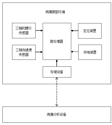
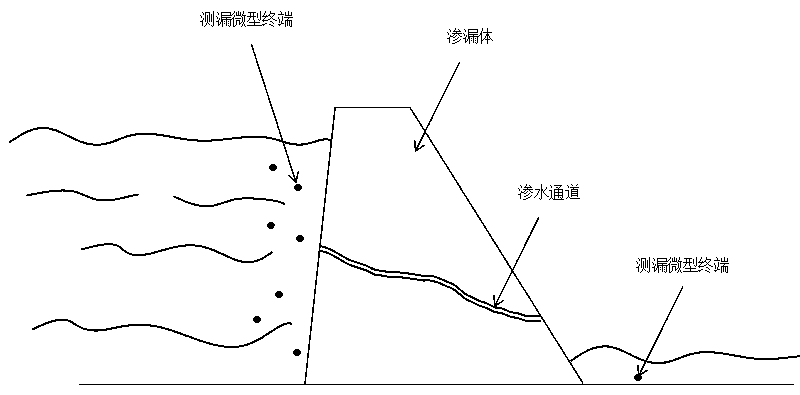
[0023] In this example, if figure 1 As shown, a leakage channel detection system based on motion trajectory analysis includes a plurality of leak detection miniature terminals and leak detection analysis equipment. The leak detection miniature terminal includes a leak detection housing and a space fixed in the leak detection housing Motion trajectory recording module, the leak detection micro-terminal is thrown on the high water level side and reaches the low water level measurement through the seepage channel on the leakage body, and the leakage detection analysis equipment is used to collect the motion trajectory parameters stored in the micro leak detection terminal, and according to the collected motion trajectory Locate the ...


PUM


Abstract

The invention discloses a leakage channel detection system and method based on motion trail analysis. The system comprises a plurality of leakage detection micro terminals and leakage detection analysis equipment, wherein the leakage detection micro terminal comprises a leakage detection shell and a space motion trail recording module fixedly arranged in the leakage detection shell, the leakage detection micro terminal is thrown to a high water level side, flows through a leakage channel in a leakage body, and reaches a low water level side, and the motion trail parameters stored in the microleakage detection terminal are collected through the leakage detection analysis equipment. According to the invention, the leakage detection micro terminals are used for collecting the space motion trail from the high water level side to the low water level side through the leakage channel of the leakage body, and the space motion trail analysis is carried out through the leakage detection analysis equipment, so that information such as the inlet position, the outlet position, the leakage track and the like of the leakage channel of the leakage body is obtained, and a basis is provided for formulating leakage treatment measures of the leakage body; and the system is clear in scheme principle, simple to operate, accurate in test and applicable to concentrated leakage channel detection and analysis of most common leakage bodies such as dams, embankments and the like.

Description

technical field [0001] The invention relates to the fields of water conservancy and hydropower, geotechnical engineering, etc., and in particular to a leakage channel detection system and method based on motion track analysis. Background technique [0002] In the construction of dams, tunnels (holes), underground powerhouses, mine shafts, subways and other projects, different types of water leakage are often encountered. Leakage will not only bring economic losses to the built reservoirs (dams), but also may threaten the safety of dams, such as the Montrek Dam and Camaraza Dam in Spain, the Gran Charevo Dam in the former Yugoslavia, and the United States. Reservoir dams such as Harasba Dam and Dapuba Dam, my country's Shandong Shore Reservoir, Hunan Fangyuan Reservoir, and Guangxi Bagong Hydropower Station cannot store water for a long time due to a large amount of water leakage, or barely store water for operation at low water levels; Water seepage from (soil) stone cofferda...

Claims


Application Information

Patent Timeline
Patent Type & Authority Applications(China)
IPC IPC(8): G01M3/20G01C21/12
CPCG01C21/12G01M3/20
Inventor 黄立维符平邢占清傅睿智
Owner CHINA INST OF WATER RESOURCES & HYDROPOWER RES
Learn More