Vomit receiving device used in gastroenterology department
A technology for receiving devices and vomit, which is applied in the direction of receiving saliva, can solve the problems of increasing the workload of medical staff and cumbersome cleaning steps, and achieve the effects of ensuring cleanliness, facilitating re-sampling, and reducing the number of cleaning times
- Summary
- Abstract
- Description
- Claims
- Application Information
AI Technical Summary
Problems solved by technology
Method used
Image
Examples
Embodiment 1
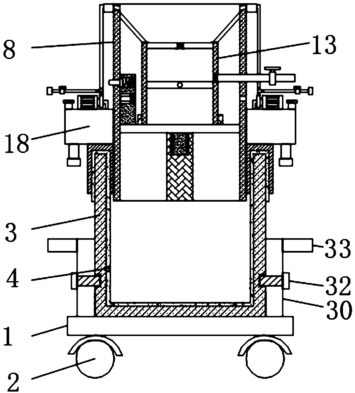
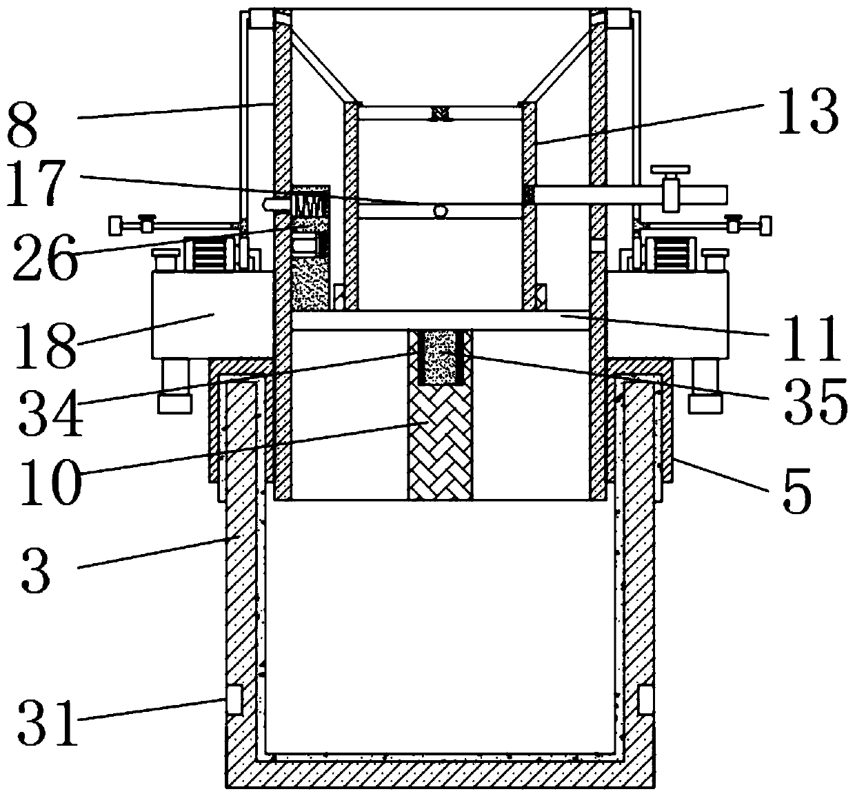
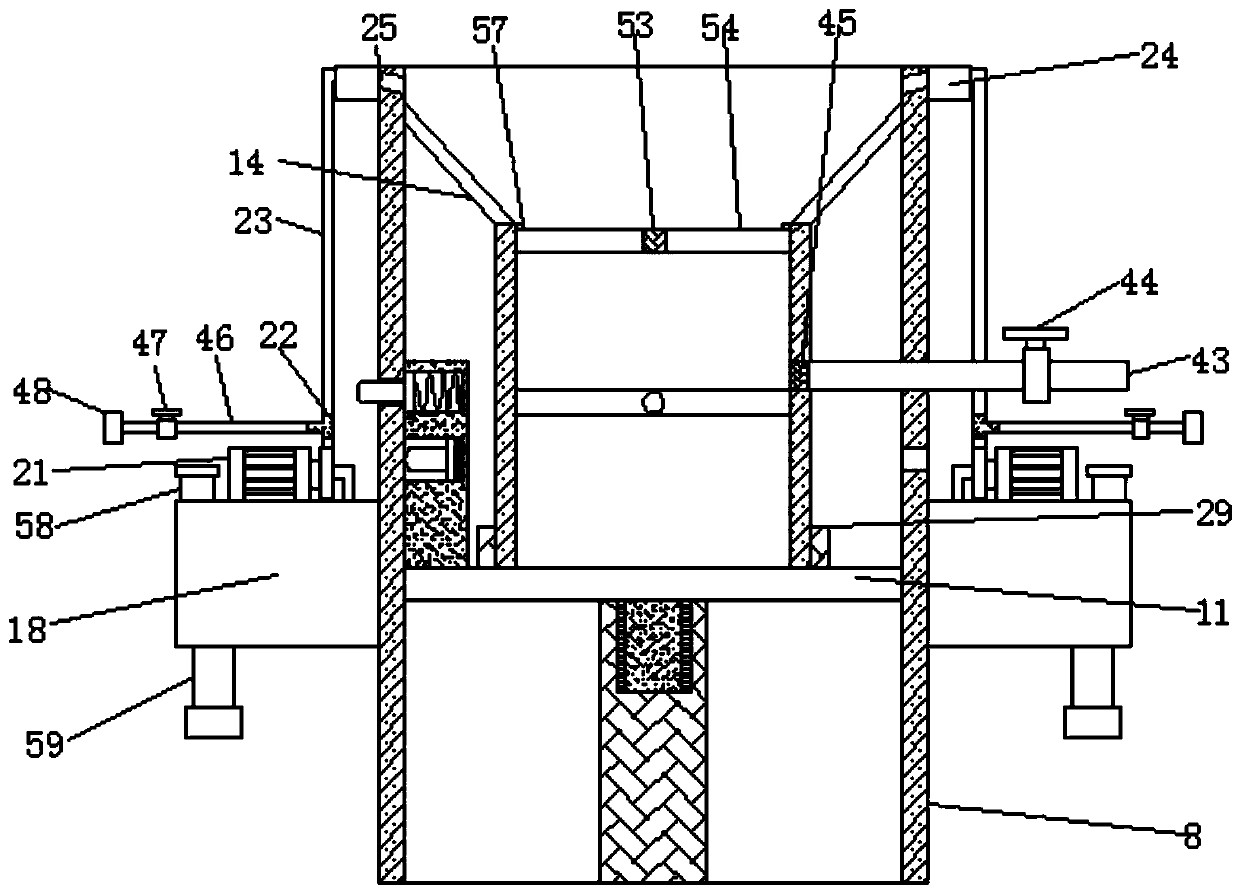
[0042] see Figure 1-13 According to an embodiment of the present invention, a vomit receiving device for gastroenterology includes a base 1, universal wheels 2 are fixedly connected to the four corners of the bottom of the base 1, and a storage tank 3 is placed on the top of the base 1, A limit mechanism is arranged between the storage tube 3 and the base 1, the inside of the storage tube 3 is covered with a garbage bag 4, and the top of the garbage bag 4 is located on the outside of the storage tube 3, so The top of the storage tube 3 is provided with a ring 5, and the bottom of the ring 5 is provided with an annular groove 6, and the top of the storage tube 3 is located in the annular groove 6 and matches with the annular groove 6 ;
[0043] The inner wall of the ring 5 is provided with an internal thread 7, the inside of the ring 5 is provided with a support tube 8, and the outer surface of the bottom of the support tube 8 is provided with an external thread 9, and the in...
Embodiment 2
[0049] see figure 1 , the limiting mechanism includes a limiting sleeve 30, a through hole 31, a bolt 32 and a connecting ring 1 33, the top of the base 1 is fixedly connected to the limiting sleeve 30, and the limiting sleeve 30 is located in the storage tube 3 Bolts 32 are threaded on the surface of the limiting sleeve 30, and a through hole 31 is opened on the outside of the storage tube 3 near the bolt 32, and the through hole 31 is connected to the port of the bolt 32. Matching, the top of the limit sleeve 30 is fixedly connected with a connecting ring one 33, and the limit mechanism can limit the storage tube 3, thereby improving the connection stability between the storage tube 3 and the base 1, so that the storage tube 3 can move together with the base 1, and the storage tank 3 cannot be easily separated from the base 1.
Embodiment 3
[0051] see Figure 5-6 , the fixing mechanism includes a fixing block 36, a limit hole 37, a limit hole 2 38, a movable rod 39, a spring 40, a connecting block 41 and a connecting block 2 42, and the rotating block 16 is above the support The outer wall of cylinder 8 is fixedly connected with fixed block 36, and the interior of described fixed block 36 is provided with movable rod 39, and the top of described movable rod 39 is fixedly connected with connecting block one 41, and the side wall of described rotating block 16 is limited Hole one 37 and the second limiting hole 38, the port of the movable rod 39 is matched with the first limiting hole 37 and the second limiting hole 38, the outer surface of the movable rod 39 is located on the The bottom of the fixed block 36 is fixedly connected with a connecting block two 42, and a spring one 40 is connected between the two connecting block 42 and the fixed block 36, and the spring one 40 is wrapped around the outer surface of th...
PUM
 Abstract
Description
Claims
Application Information
 - Generate Ideas
- Intellectual Property
- Life Sciences
- Materials
- Tech Scout
- Unparalleled Data Quality
- Higher Quality Content
- 60% Fewer Hallucinations
Browse by: Latest US Patents, China's latest patents, Technical Efficacy Thesaurus, Application Domain, Technology Topic, Popular Technical Reports.
© 2025 PatSnap. All rights reserved.Legal|Privacy policy|Modern Slavery Act Transparency Statement|Sitemap|About US| Contact US: help@patsnap.com


