Eureka AIR delivers breakthrough ideas for toughest innovation challenges, trusted by R&D personnel around the world.

Computer graphics rendering using boundary information

Inactive Publication Date: 2005-01-27
THE BOARD OF TRUSTEES OF THE LELAND STANFORD JUNIOR UNIV
View PDF14 Cites 38 Cited by
  • Summary
  • Abstract
  • Description
  • Claims
  • Application Information

AI Technical Summary

Benefits of technology

In one aspect, the present invention provides a new graphics rendering technique that renders textures of various types in real time with improved texture rendering at high magnification levels. Specifically, the techniques accurately render shadow boundaries and other boundaries within highly magnified textures without blurring or pixelation artifacts. Moreover, the techniques can be implemented in existing graphics hardware in constant time, have bounded complexity, and do not require large amounts of memory.
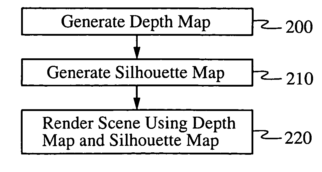
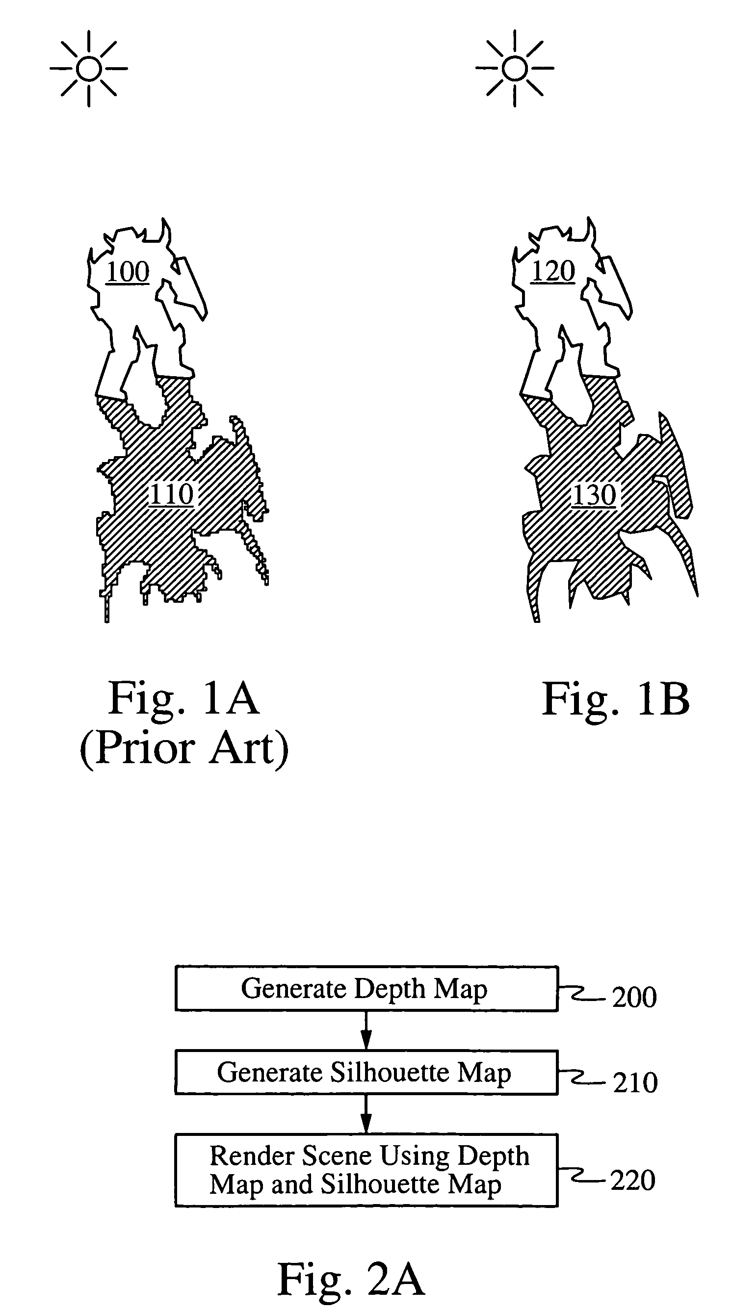
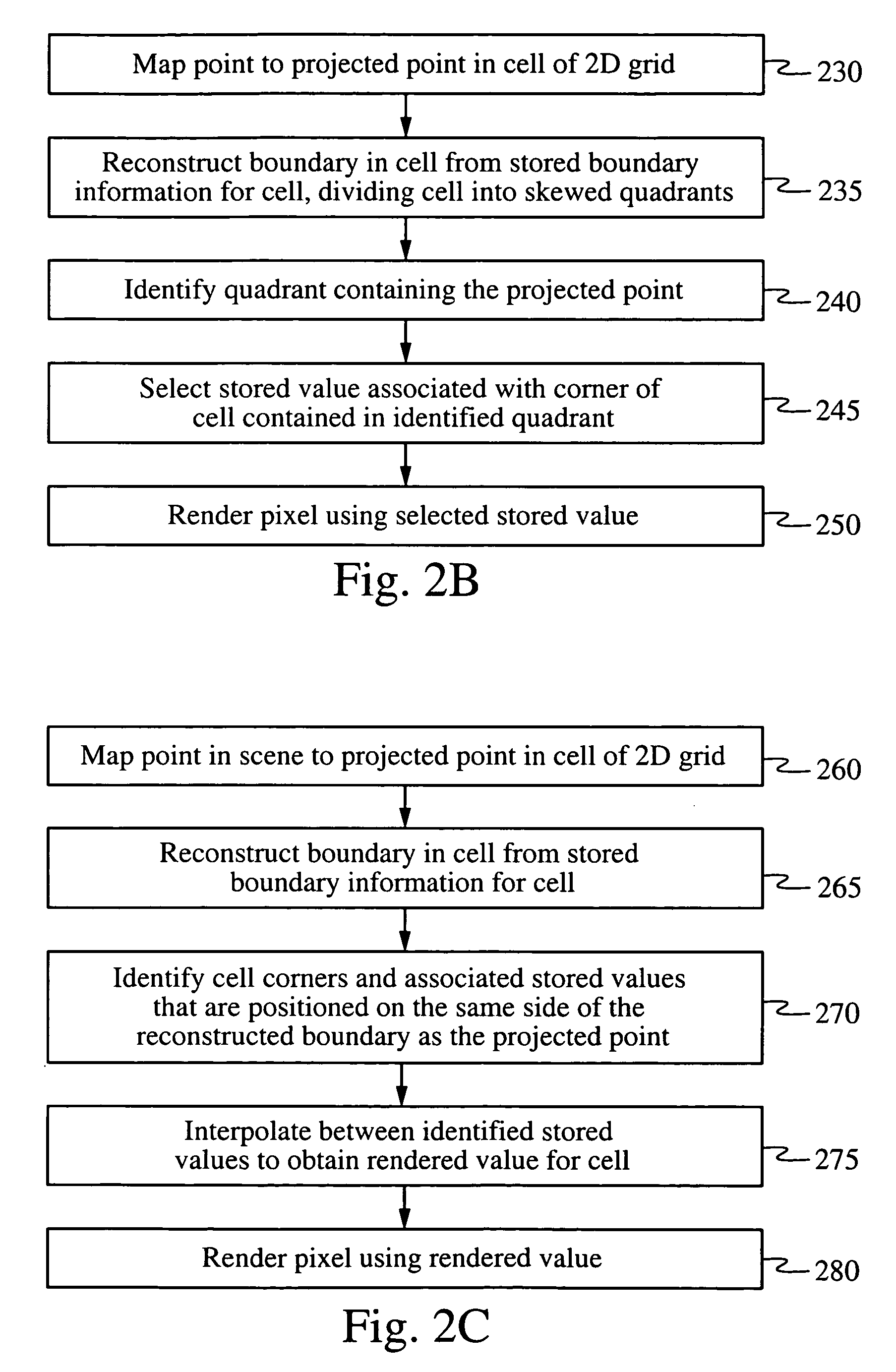
According to one aspect, the method uses a novel silhouette map to improve texture mapping. The silhouette map, also called a silmap, embodies boundary position information which enables a texture to be mapped to a rendered image under high magnification without blurring or pixelation of boundaries between distinct regions within the texture. In one embodiment, the texture is a bitmap texture and the silmap contains boundary information about the position of boundaries between differently colored regions in the texture. In another embodiment, the texture is a depth map and the silmap contains boundary information about the position of shadow boundaries. In some embodiments, the silmap and the texture are represented by two arrays of values, corresponding to a pair of two-dimensional grids of cells. In a preferred embodiment, the two grids are offset by one-half of a cell width and the boundary information of each cell in the silmap comprises coordinates of a boundary point in the cell. In another embodiment, the boundary information in the silmap cells comprise grid deformation information for the texture grid. In a preferred embodiment, the representation of the silmap satisfies two main criteria. First, the representation preferably provides information sufficient to reconstruct a continuous boundary. Second, the information preferably is easy to store and sample.

Problems solved by technology

These and other desirable properties of rendering, however, can introduce substantial computational complexity which introduces problems due to practical limitations in computational resources.
Therefore, it is a significant challenge in the art of computer graphics to discover rendering techniques that are both practical to implement and provide realistic results.
This mapping process, however, can result in undesirable artifacts in the rendered image, especially when the texture's grid does not correspond well with the grid of pixels in the rendered image.
This mismatch can be especially pronounced when the object is magnified or minified (i.e., viewed up close or very far away).
Rendering magnified textures without artifacts, however, remains a problem.
Because textures are discrete data structures, highly magnifying a texture results in noticeable pixelation artifacts in the rendered image, i.e., the appearance of jagged color discontinuities in the image where there should not be any.
Interpolation, however, results in a blurry rendered image lacking definition.
The brute-force approach of simply storing higher resolution textures increases memory requirements and can also increase computational complexity if compressed textures are used.
Similar problems exist when rendering shadows.
These depth map textures, however, have the same rendering problems as the previously discussed textures.
Specifically, when the grid of the depth map texture does not correspond well with the grid of pixels in the rendered image rendering artifacts appear.
In particular, under high magnification the shadow boundaries in the rendered image will be jagged or, if a filtering technique is used, the shadow boundaries will be very blurry.

Method used


Image

  • Computer graphics rendering using boundary information
  • Computer graphics rendering using boundary information
  • Computer graphics rendering using boundary information

Examples


Embodiment Construction

The techniques of the present invention, like other graphical rendering techniques, may be implemented in a variety of ways, as is well known in the art. For example, they may be implemented in hardware, firmware, software, or any combination of the three. To give just one concrete example, the technique may be implemented on the ATI Radeon 9700. Pro using ARB_vertex_program and ARB_fragment_program shaders. It is an advantage of the present invention that the rendering techniques may be efficiently implemented in current graphics hardware. In addition, they have constant time and bounded complexity.

Those skilled in the art of computer graphics will appreciate from the present description that the techniques of the present invention have many possible implementations and embodiments. Several specific embodiments will now be described in detail to illustrate the principles of the invention. First, we will describe embodiments related to shadow rendering, followed by embodiments re...


PUM


Abstract

A method for computer graphics rendering system uses a silhouette map containing boundary position information that is used to reconstruct precise boundaries in the rendered image, even under high magnification. In one embodiment the silhouette map is used together with a depth map to precisely render the edges of shadows. In another embodiment, the silhouette map is used together with a bitmap texture to precisely render the borders between differently colored regions of the bitmap. The technique may be implemented in software, on programmable graphics hardware in real-time, or with custom hardware.

Description

FIELD OF THE INVENTION The present invention relates to computer graphics rendering techniques. More specifically, it relates to improved methods for faithfully rendering boundaries such as shadow silhouette boundaries and texture boundaries. BACKGROUND OF THE INVENTION In the field of computer graphics, considerable research has focused on rendering, i.e., the process of generating a two-dimensional image from a higher-dimensional representation, such as a description of a three-dimensional scene. For example, given a description of a three-dimensional object, a rendering method might generate a two-dimensional image for display on a computer screen. A desirable rendering method generates a two-dimensional image that is a faithful and realistic rendering of the higher-dimensional scene. For example, a desirable rendering should be a correct perspective view of the scene from a particular viewpoint, it should appropriately hide portions of objects that are behind other objects in ...

Claims


Application Information

Patent Timeline
IPC IPC(8): G06T15/20
CPCG06T15/04
Inventor SEN, PRADEEPCAMMARANO, MICHAELHANRAHAN, PATRICK M.
Owner THE BOARD OF TRUSTEES OF THE LELAND STANFORD JUNIOR UNIV
Why Eureka
Eureka Blog
Learn More