
Chip packaging method and chip packaging structure

A chip packaging structure and chip packaging technology, applied in radiation control devices, semiconductor devices, electrical components, etc., can solve the problems of complicated procedures and high packaging requirements, and achieve good photosensitive effect, use less materials, and reduce the number of refractions Effect

Active Publication Date: 2021-03-26
FOREHOPE ELECTRONICS NINGBO CO LTD
View PDF4 Cites 0 Cited by
  • Summary
  • Abstract
  • Description
  • Claims
  • Application Information

AI Technical Summary

Problems solved by technology

However, the existing production method has too high requirements for packaging, and the process is too complicated, which poses new challenges to the quality and efficiency control of mass production.

Method used


Image

  • Chip packaging method and chip packaging structure
  • Chip packaging method and chip packaging structure
  • Chip packaging method and chip packaging structure

Examples


Embodiment Construction

[0025] The technical solutions in the embodiments of the present application will be described below with reference to the drawings in the embodiments of the present application.

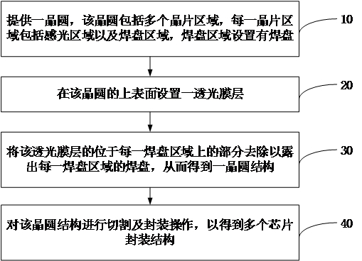
[0026] The embodiment of the present application provides a chip packaging method, which can be used in the packaging process of light-transmitting chips (CIS chips). chip package. figure 1 shows a flowchart of a chip packaging method, as figure 1 As shown, the chip packaging method includes:

[0027] Step 10: providing a wafer, the wafer includes a plurality of wafer areas, each wafer area includes a photosensitive area and a pad area, and the pad area is provided with pads.

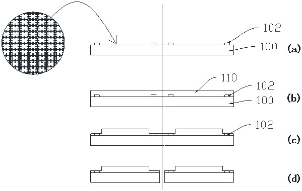
[0028] figure 2 A schematic diagram of a wafer is shown, and the wafer 100 includes a plurality of wafer regions 101 , and each wafer region 101 is fabricated with required integrated functional circuits, and the integrated functional circuits convert sensed optical signals into electrical signals. The wafer 100 includes...


PUM

PropertyMeasurementUnit
thicknessaaaaaaaaaa
transmittivityaaaaaaaaaa

Abstract

The invention provides a chip packaging method and a chip packaging structure, and relates to the technical field of chip packaging. The chip packaging method comprises the steps: providing a wafer, wherein the wafer comprises a plurality of wafer areas, each wafer area comprises a photosensitive area and a bonding pad area, and bonding pads are arranged in the bonding pad areas; arranging a light-transmitting film layer on the upper surface of the wafer; removing the part, located on each bonding pad region, of the light-transmitting film layer so as to expose the bonding pad of each bondingpad region, so that a wafer structure is obtained; and cutting and packaging the wafer structure to obtain a plurality of chip packaging structures. Compared with other packaging methods, the chip packaging method provided by the invention has the advantages that the processing flow is short, the process control difficulty is low, the obtained packaging body is thin, and fewer materials are used.

Description

technical field [0001] The present application relates to the technical field of chip packaging, and in particular, to a chip packaging method and a chip packaging structure. Background technique [0002] CIS (Contact Image Sensor), also known as contact image sensor, is a new type of line image sensor, which is a photoelectric coupling device researched and developed after CCD (Charge-coupled Device, charge-coupled device) in recent years. It can perceive optical signals and convert them into electronic signals carrying image information. As such a processing electronic device, it has a wide range of applications in the market, such as in smart terminals, cameras, scanning situational awareness, etc. . At the beginning of the design of this kind of device, in order to improve the imaging quality and practicability of the product, it generally needs to be packaged and then installed in the terminal equipment. [0003] At present, the traditional packaging structure mainly ...

Claims


Application Information

Patent Timeline
Patent Type & Authority Patents(China)
IPC IPC(8): H01L27/146
CPCH01L27/1462H01L27/14625H01L27/14678H01L27/14685
Inventor 庞宏林钟磊李利
Owner FOREHOPE ELECTRONICS NINGBO CO LTD
Learn More