Bearing defect rapid detection device for industrial robot and detection method thereof
A technology of industrial robots and detection devices, applied in measuring devices, optical testing flaws/defects, instruments, etc., can solve problems such as inability to detect, low detection efficiency, poor detection effect, etc., to avoid detection errors and improve detection accuracy , the effect of improving work efficiency
- Summary
- Abstract
- Description
- Claims
- Application Information
AI Technical Summary
Problems solved by technology
Method used
Image
Examples
Embodiment 1
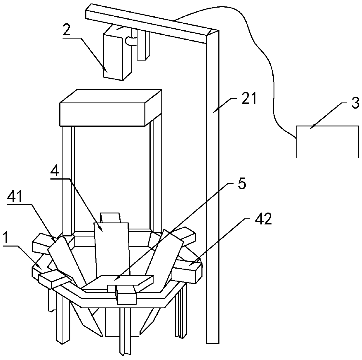
[0037] Such as figure 1As shown, the present invention discloses a quick detection device for bearing defects of industrial robots. In the specific embodiment of the present invention, it includes a frame 1, a matrix camera 2, a control panel 3, a plane mirror assembly 4 and a light supplement 5; The matrix camera 2 is installed on the frame 1 by the lifting frame 21 and is electrically connected with the control panel 3; the frame 1 directly below the matrix camera 2 is provided with a detection platform 5. Evenly installed on 5 circles of the detection platform; the plane mirror 41 is installed on the frame 1 through the plane mirror bracket 42; the light supplement 5 is installed on the frame 1 through the light supplement bracket 51.
[0038] Compared with the prior art, the beneficial effects brought by the present invention are: compared with the traditional line scan camera used for bearing surface detection and observation, the device adopts a rectangular camera for su...
Embodiment 2
[0039] Embodiment 2, the difference with embodiment 1 is
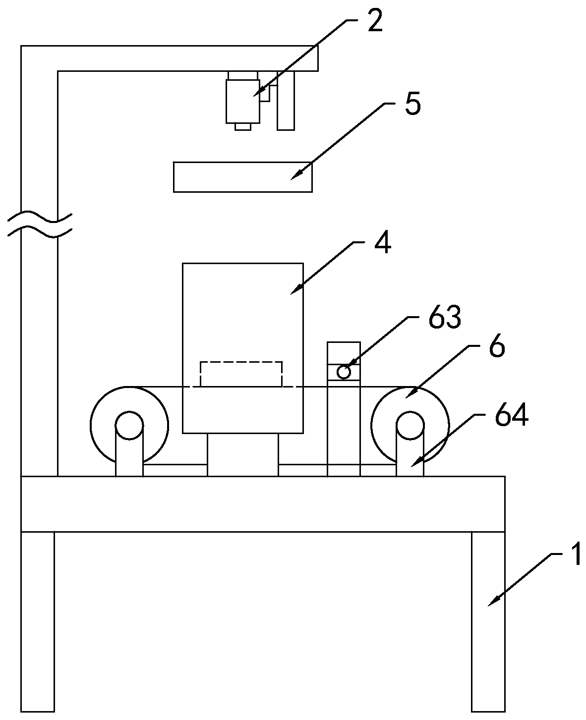
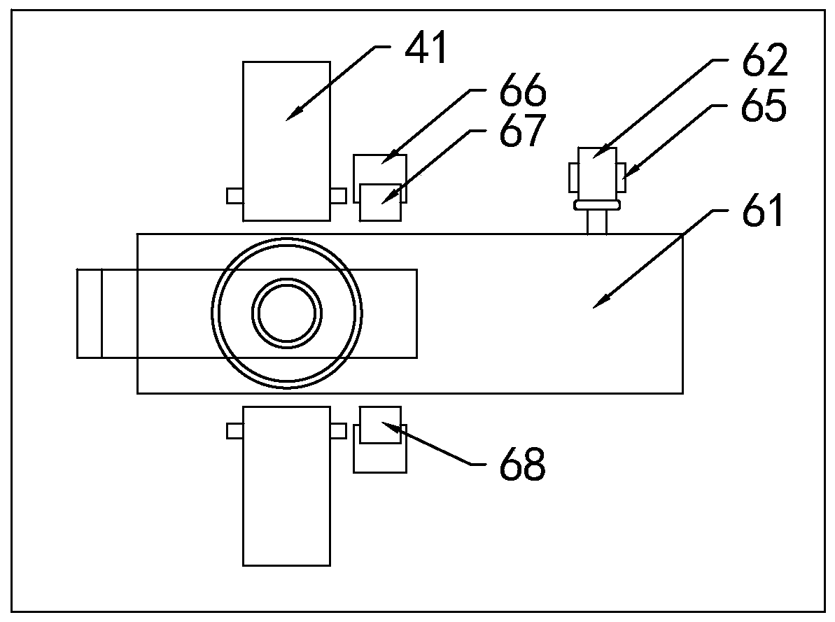
[0040] Such as Figure 2-4 As shown, in the specific embodiment of the present invention, a transport positioning device 6 for transporting bearings is installed on the frame 1 directly below the matrix camera 2; at least two plane mirrors 41 are installed on both sides of the transport positioning device 6.
[0041] The transport positioning device 6 includes a conveyor belt 61, a servo motor 62 for driving the conveyor belt 61, and a laser detector 63; the conveyor belt 61 is installed on the frame 1 through a conveyor belt mounting frame 64; Installed on the frame 1 and the output end is fixedly connected to the driving shaft of the conveyor belt 61; the laser detector 63 is installed on the frame 1 by the detector support 66, and is positioned at the side of the matrix camera 2 toward the input end of the conveyor belt 61; The laser detector 63 includes a laser generator 67 and a laser receiver 68 installed on the...
Embodiment 3
[0044] Embodiment 3, the difference with embodiment 2 is
[0045] Such as Figure 5-6 As shown, in the specific embodiment of the present invention, the shown plane mirror 41 is installed on the frame 1 through the mirror surface adjustment part 7; The height of the lifting unit 72 and the vertical axis rotation unit 73 and the horizontal axis rotation unit 74 for adjusting the mirror angle of the plane mirror; the lifting unit 72 is installed on the mounting base 71, and the vertical axis rotation unit 73 is installed on the lifting unit 72 output end; the horizontal axis rotation unit 74 is installed on the vertical rotation unit 73 .
[0046] In a specific embodiment of the present invention, the lifting unit 72 includes a lower support body 721, an upper support body 722, an extrusion ring 723 and a positioning screw cover 724; the lower support body 721 is a hollow cylinder, and the upper support body 722 is Tubular; and one end of the lower support body 721 is fixedly ...
PUM
 Abstract
Description
Claims
Application Information
 - R&D
- Intellectual Property
- Life Sciences
- Materials
- Tech Scout
- Unparalleled Data Quality
- Higher Quality Content
- 60% Fewer Hallucinations
Browse by: Latest US Patents, China's latest patents, Technical Efficacy Thesaurus, Application Domain, Technology Topic, Popular Technical Reports.
© 2025 PatSnap. All rights reserved.Legal|Privacy policy|Modern Slavery Act Transparency Statement|Sitemap|About US| Contact US: help@patsnap.com


