Heat storage and heat exchange linked heating furnace and operation method thereof
What is Al technical title?
Al technical title is built by PatSnap Al team. It summarizes the technical point description of the patent document.
An operation method and technology of heating furnaces, which are applied in the direction of lighting and heating equipment, furnaces, furnace types, etc., can solve problems such as heat storage capacity decline, energy waste, and air hole blockage, so as to improve service life, reduce power consumption, and avoid secondary secondary burning effect
Inactive Publication Date: 2020-08-11
ZHANGJIAGANG HONGCHANG STEEL PLATE CO LTD +2
View PDF5 Cites 2 Cited by
Summary
Abstract
Description
Claims
Application Information
AI Technical Summary
This helps you quickly interpret patents by identifying the three key elements:
Problems solved by technology
Method used
Benefits of technology
Problems solved by technology
When this kind of combustion technology is reversing, the moment the gas reversing valve changes from gas supply to gas extraction, the burner, reversing valve and the pipeline between the two are still full of gas due to the existence of gas residual pressure. When the gas mixes with the residual oxygen in the high-temperature flue gas entering the burner after reversing, secondary combustion occurs instantly, and the regenerator in the burner will appear melting, sticking, cracking, deformation, and porosity under the high temperature of the flame. Clogging and other phenomena, resulting in a decrease in heat storage capacity
The gas that has not undergone secondary combustion is discharged together with the flue gas, resulting in a waste of energy
Method used
Image
Click on the blue label to locate the original text in one second.
Reading with bidirectional positioning of images and text.
Examples
Embodiment Construction
[0027] The technical solutions in the embodiments of the present invention will be described in detail below, obviously, the described embodiments are only some of the embodiments of the present invention, but not all of the embodiments. Based on the embodiments of the present invention, all other embodiments obtained by persons of ordinary skill in the art without making creative efforts belong to the protection scope of the present invention.
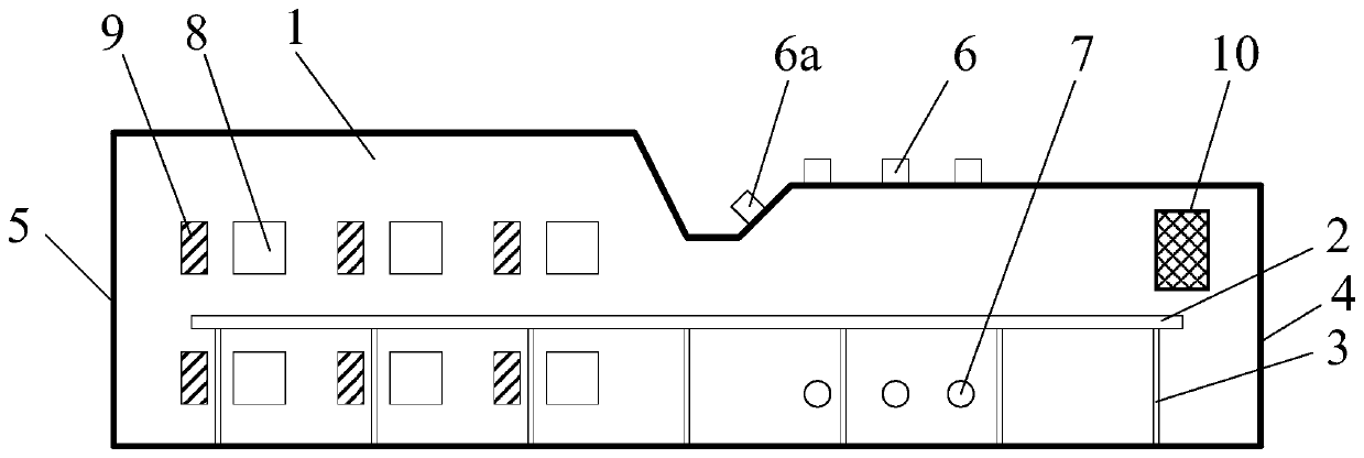
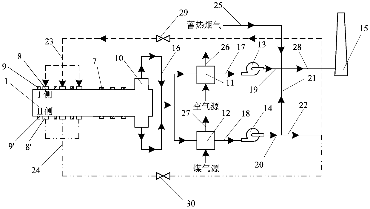
[0028] see figure 1 and figure 2 , The heating furnace is divided into the first heating section, the second heating section and the third heating section along the furnace length direction, and is divided into I side and II side along the width direction. The roof of the first heating section is lower than the roof of the third heating section. The roof area of the second heating section is concave, lower than the first and third heating sections. The flat flame burner 6 is installed on the top of the first heating section, and...
PUM
Abstract
The invention discloses a heat storage and heat exchange linked heating furnace and an operation method thereof. The heat storage and heat exchange linked heating furnace comprises a hearth, a steel tapping furnace door, a steel input furnace door, a flue ad a stepping beam mounted in the hearth. The hearth is divided into a first heating section, a second heating section and a third heating section along the side from the steel input furnace door to the steel tapping furnace door, a first flat flame burner is mounted at the position, on the first heating section, of the top of the hearth, andflame adjusting burners are mounted on the two sides of the position, on the first heating section, of the hearth. Heat storage type burners are mounted on the two sides of the position, on the thirdheating section, of the hearth. The horizontal height of the top of the position, of the first heating section, of the hearth is lower than that of the position, of the third heating section, of thehearth. The top of the position, on the second heating section, of the hearth is concaved downwards to form a U shape from the position, on the first heating section, of the top of the hearth to the position, on the third heating section, of the top of the hearth. According to the heat storage and heat exchange linked heating furnace and the operation method thereof, the problem of large heat storage type furnace pressure and secondary combustion in a coal gas burner is effectively relieved.
Description
technical field [0001] The application belongs to the fields of heating furnace equipment, regenerative combustion technology and heat exchanger equipment, and in particular relates to a heating furnace combined with heat storage and heat exchange and its operating method. Background technique [0002] In the prior art, the regenerative heating furnace adopts an efficient regenerative heat exchange device to maximize the recovery of the sensible heat in the high-temperature flue gas for preheating the gas and combustion-supporting air to obtain a high temperature above 1000°C. The heating furnace adopting regenerative combustion technology can reduce the temperature of the high-temperature flue gas discharged from the furnace to below 150°C, and the heat recovery rate can reach more than 85%; and make effective use of low calorific value fuels such as blast furnace gas. However, due to the inherent characteristics of regenerative combustion, there are some problems during op...
Claims
Application Information
Patent Timeline
Application Date:The date an application was filed.
Publication Date:The date a patent or application was officially published.
First Publication Date:The earliest publication date of a patent with the same application number.
Issue Date:Publication date of the patent grant document.
PCT Entry Date:The Entry date of PCT National Phase.
Estimated Expiry Date:The statutory expiry date of a patent right according to the Patent Law, and it is the longest term of protection that the patent right can achieve without the termination of the patent right due to other reasons(Term extension factor has been taken into account ).
Invalid Date:Actual expiry date is based on effective date or publication date of legal transaction data of invalid patent.