Concrete mixing plant for hydraulic engineering construction

A technology of mixing equipment and water conservancy engineering, which is applied in cement mixing devices, clay preparation devices, batching weighing instruments, etc., can solve the problems of inability to dissipate heat from concrete in mixing drums, without raw material weighing and measurement, and large raw material ratio errors. , to achieve the effect of reducing dust splashing, increasing sealing and easy control

Pending Publication Date: 2020-08-11
刘伟
View PDF10 Cites 0 Cited by
  • Summary
  • Abstract
  • Description
  • Claims
  • Application Information

AI Technical Summary

Problems solved by technology

[0002] Hydraulic engineering is a general term for various engineering constructions to control, utilize and protect surface and underground water resources and the environment. The construction of hydraulic engineering equipment is inseparable from the use of concrete. When concrete is used, It is necessary to add water and mix all kinds of raw materials evenly to meet the conditions of use. When mixing concrete, traditional mixing equipment cannot effectively dissipate heat from the mixing drum and the concrete inside, resulting in false coagulation of concrete due to excessive temperature. Moreover, the existing concrete mixing equipment does not have the function of weighing and measuring raw materials, which makes it difficult for construction personnel to control the amount of raw materials added, resulting in large errors in raw material ratios, which will lead to poor quality concrete produced

Method used


Image

  • Concrete mixing plant for hydraulic engineering construction
  • Concrete mixing plant for hydraulic engineering construction
  • Concrete mixing plant for hydraulic engineering construction

Examples


Embodiment 1

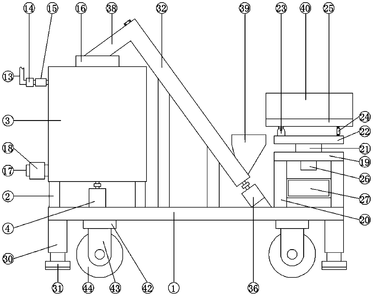
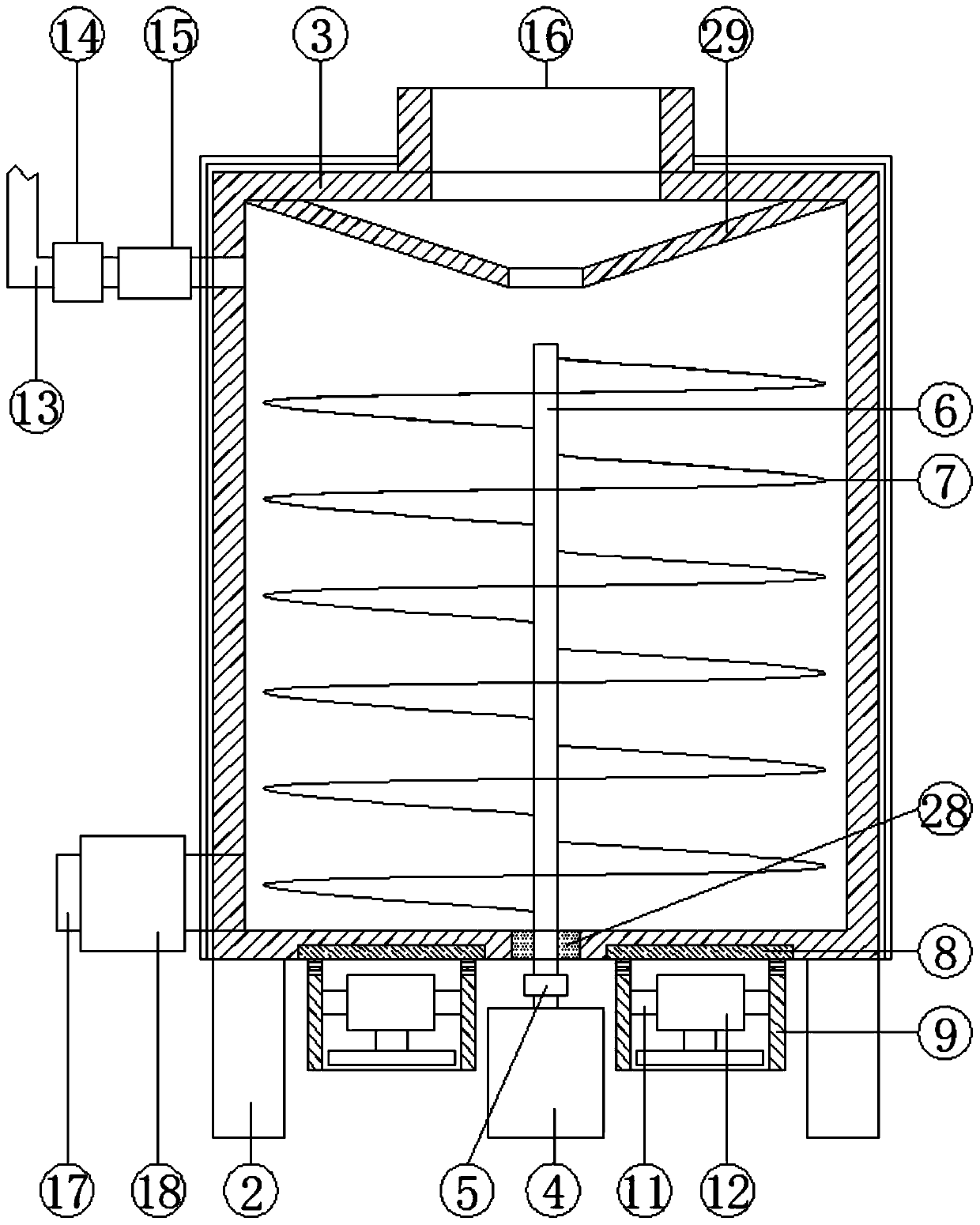
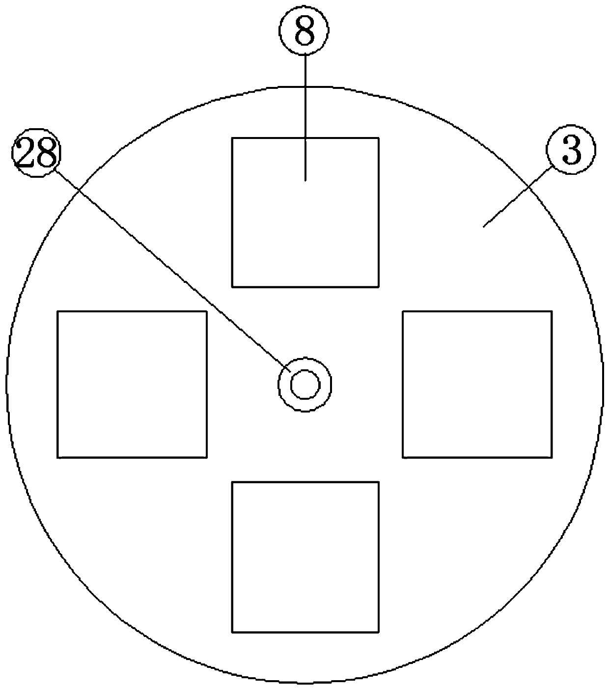
[0035] see Figure 1-6According to an embodiment of the present invention, a concrete mixing equipment for hydraulic engineering construction includes a base 1, a mixing drum 3 is fixed on the base 1 through a first connecting rod 2, and a first motor is fixed on the base 1 4. The rotating shaft of the first motor 4 is fixed with a transmission shaft 6 through the first coupling 5, and the transmission shaft 6 penetrates the bottom end of the mixing drum 3 and extends into the mixing drum 3, and the transmission shaft 6 The outer wall of the upper end of the shaft 6 is fixed with a number of spiral stirring blades 7, and the outer wall of the bottom end of the mixing drum 3 is fixedly embedded with four semiconductor refrigerators 8 at equal intervals along the circumferential direction. There is a cylinder 9, the upper end of the cylinder 9 is provided with a number of air intake holes 10, the inside of the cylinder 9 is fixed with a cooling fan 12 through the second connecti...

Embodiment 2

[0038] see Figure 1-2 , for the mixing drum 3, the middle part of the bottom end of the mixing drum 3 is fixedly embedded with a sealing ring 28 and the sealing ring is sleeved on the outer wall of the transmission shaft 6; for the mixing drum 3, the upper end of the mixing drum 3 The inner wall is fixed with a splash-proof tube 29, and the splash-proof tube 29 is a hollow inverted round table-shaped structure; for the mixing drum 3, the outer wall of the mixing drum 3 is fixed with sound-absorbing cotton, and the outer wall of the sound-absorbing cotton is fixed with Sound insulation cotton.

[0039] Through the above scheme of the present invention, the sealing ring 28 can increase the sealing between the transmission shaft 6 and the bottom end of the mixing drum 3, and the splash-proof drum 29 can effectively reduce the dust splashing during the stirring process, thereby improving the working environment and sound absorption. Cotton and sound insulation cotton can absorb ...

Embodiment 3

[0041] see figure 1 , 5 and 6, for the feeding device, the feeding device includes a feeding tube 32, the feeding tube 32 is fixed on the base 1 through several third connecting rods, and the inside of the feeding tube 32 can be rotated A rotating shaft 33 is provided, the outer wall of the rotating shaft 33 is fixed with dragon blades 34, the base 1 is fixed with a motor mount 35, and the motor mount 35 is fixed with a second motor 36. The rotating shaft of two motors 36 is fixedly connected with the lower end of the rotating shaft 33 through the second coupling 37, the upper end of the feeding cylinder 32 is connected with a discharge pipe 38 and the lower end of the discharge pipe 38 is connected with the feed inlet 16 connected, the lower end of the feeding tube 32 is fixed with a hopper 39, and the storage plate 25 is matched with the hopper 39; for the storage plate 25, both sides of the storage plate 25 are fixed with side plate 40 , and an end plate 41 is fixed at th...


PUM


Abstract

The invention discloses concrete mixing plant for hydraulic engineering construction. The concrete mixing plant for the hydraulic engineering construction comprises a base, a mixing barrel is fixedlyarranged on the base through a first connecting rod, a first motor is fixedly arranged on the base, a transmission shaft is fixedly arranged on a rotating shaft of the first motor through a first coupler, the transmission shaft penetrates through the bottom end of the mixing barrel and extends into the mixing barrel, a plurality of spiral stirring blades are fixedly arranged on the outer wall of the upper end of the transmission shaft, and four semiconductor coolers are fixedly embedded in the outer wall of the bottom end of the mixing barrel at equal intervals in the circumferential direction. The concrete mixing plant for the hydraulic engineering construction has the beneficial effects that the mixing barrel and concrete can be effectively cooled when the concrete is stirred, so that the phenomenon of false setting of the concrete due to over-high temperature can be avoided, a raw material can be weighed and metered, the addition amount of the raw material can be conveniently controlled, the raw material can be strictly added according to a scientific ratio, and therefore, the quality of the produced concrete can be ensured.

Description

technical field [0001] The invention relates to the field of hydraulic engineering construction equipment, in particular to a concrete mixing equipment for hydraulic engineering construction. Background technique [0002] Hydraulic engineering is a general term for various engineering constructions to control, utilize and protect surface and underground water resources and the environment. The construction of hydraulic engineering equipment is inseparable from the use of concrete. When concrete is used, It is necessary to add water and mix all kinds of raw materials evenly to meet the conditions of use. When mixing concrete, traditional mixing equipment cannot effectively dissipate heat from the mixing drum and the concrete inside, resulting in false coagulation of concrete due to excessive temperature. Moreover, none of the existing concrete mixing equipment has the function of weighing and measuring raw materials, which makes it difficult for construction workers to contro...

Claims


Application Information

Patent Timeline
Patent Type & Authority Applications(China)
IPC IPC(8): B28C5/16B28C7/10B28C7/12
CPCB28C5/0806B28C5/0818B28C5/16B28C7/044B28C7/10B28C7/128
Inventor 刘伟李铁山兰素银苑玉霞张字富张利民
Owner 刘伟
Why Eureka
Try Eureka