Coaxial opposite rotor differential motor and new energy automobile

A coaxial pair and differential motor technology, applied in electric vehicles, motors, motor vehicles, etc., can solve the complex structure of the hub motor and its control system, the limitation of the driving mode of the hub motor wheel side motor, the increase of vehicle structure cost and Operating costs and other issues, to achieve cost savings and process difficulty, is conducive to lightweight, save the effect of mechanical differential

Inactive Publication Date: 2020-08-07
佛山中锦微电科技有限公司
View PDF3 Cites 2 Cited by
  • Summary
  • Abstract
  • Description
  • Claims
  • Application Information

AI Technical Summary

Problems solved by technology

[0002] Existing cars all use differentials to achieve differential drive between wheel speeds. New energy electric vehicles are also equipped with the same mechanical differentials. Such a structure leads to insertion loss of differentials, reduces mechanical transmission efficiency, and exists Noise, the weight of the differential is not conducive to lightweight, increase the vehicle structure cost and operating cost, and there are problems such as maintenance period
For cars using in-wheel motors, no differential drive can be achieved, but the structure of the in-wheel motor and its control system is complex, the cost is high, the weight ratio of the body and the wheel system is also changed, the software of the inter-wheel control system is complicated, There are problems such as immature technology and operational risks, which greatly restrict the drive mode of hub motors and even wheel motors
In addition, for vehicles using permanent magnet motors, there are problems of high cost, thermally induced demagnetization, and secondary battery loss. The permanent magnet motor industry chain also has rare earth shortage resource consumption and environmental protection issues during mining and processing.

Method used


Image

  • Coaxial opposite rotor differential motor and new energy automobile
  • Coaxial opposite rotor differential motor and new energy automobile
  • Coaxial opposite rotor differential motor and new energy automobile

Examples


Embodiment 1

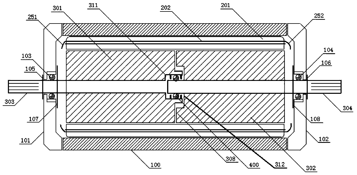
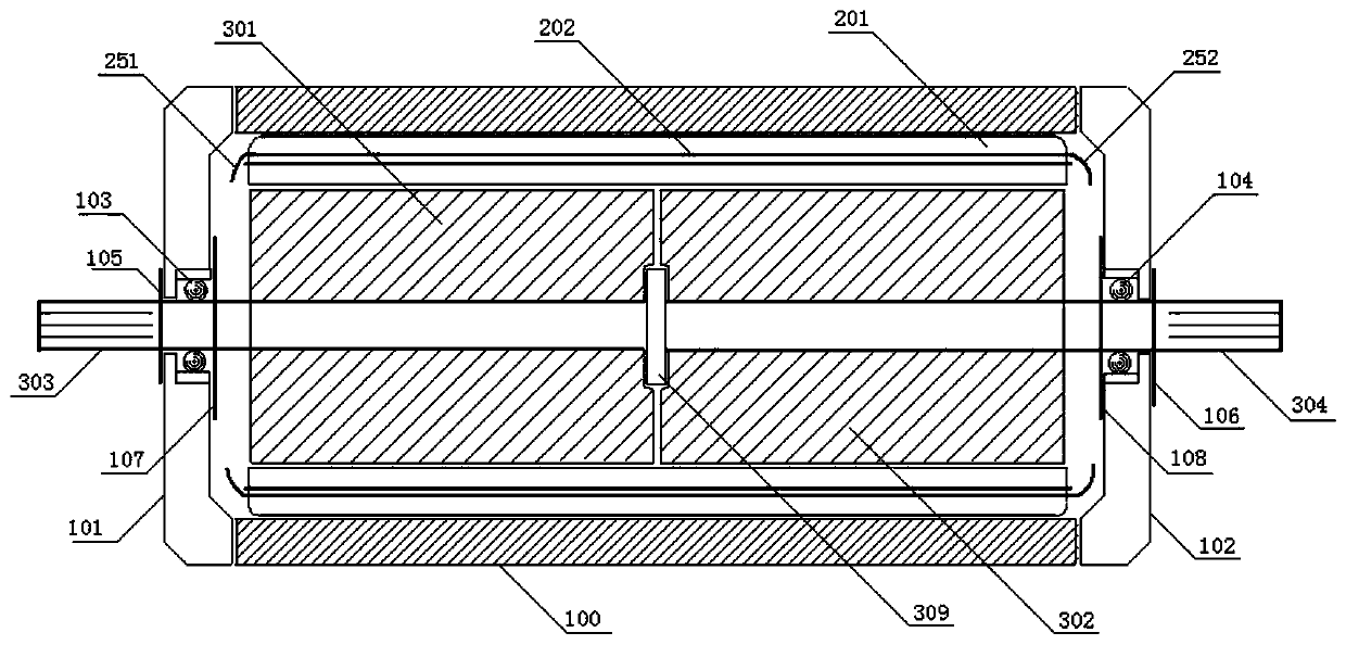
[0040] Such as figure 1 As shown, a coaxial opposed rotor differential motor includes a motor casing 100, a stator 201, a first rotor 301 and a second rotor 302 in the form of a coaxial assembly, wherein the casing part includes a left end cover 101 and right end cap 102.

[0041] The stator 201 is the stator of an asynchronous motor, including a stator core and a stator winding 202 (a part of the winding end is also shown in the figure, such as 251 and 252), the stator is assembled in the motor casing, and the stator winding is assembled on the stator core. In the slot circuit, the length of the straight conductor part of the stator winding is equal to the sum of the axial length of the effective magnetic core of the first rotor and the axial length of the effective magnetic core of the second rotor, and the magnetic field generated by the stator winding is generated by the first winding and the second winding Shared, both the first rotor and the second rotor are the rotor s...

Embodiment 2

[0049] A coaxial opposed rotor differential motor, comprising the aforementioned coaxial opposed rotor differential motor, the first output shaft of the differential motor outputs power through a speed reducer, and the second output shaft passes through another speed reducer External output power, such as Figure 8 As shown,.

[0050] It is easy to understand that the present invention also provides a coaxial opposed rotor differential motor, and an electronic control module is installed in the motor casing, which is beneficial to detect and control the current of the stator winding, realize a compact integrated design, reduce the Small electromagnetic pollution and signal and energy transmission loss.

[0051] In a second aspect, a voltage control method for a coaxial opposed-rotor differential motor is provided.

Embodiment 3

[0053] The voltage control method includes the following steps, such as Figure 9 Shown:

[0054] ① Obtain the first output shaft speed signal SP1 and the second output shaft speed signal SP2 by detecting the speed of the first output shaft and the second output shaft of the coaxial opposite rotor differential motor, and transmit the signals SP1 and SP2 to a Electronic Control Unit ECU,

[0055] ②The electronic control unit ECU compares the signals SP1 and SP2, and judges whether the speed difference reflected by the two signals exceeds the preset set value,

[0056] ③ When the speed difference reflected by the two signals does not exceed the preset set value, the electronic control unit ECU defaults to the speed difference, continues to monitor the two speed signals SP1 and SP2, and does not regulate the power supply voltage; when the speed reflected by the two signals When the difference exceeds the preset set value, the electronic control unit ECU regulates the power supp...


PUM


Abstract

A coaxial opposite rotor differential motor belongs to the electromechanical technology and automobile technology field, and comprises a motor housing, a stator, and a first rotor and a second rotor which are coaxially assembled and opposed to each other. The stator, the first rotor and the second rotor are all stator and rotor structures of an asynchronous motor. Electrical parameters of the first rotor and the second rotor are the same. The stator comprises a stator magnetic core and a stator winding, the sum of effective magnetic core lengths of the first rotor and the second rotor is equalto the length of the stator magnetic core, and a magnetic field generated by the stator winding is shared by the first rotor and the second rotor; the first rotor is provided with a first output shaft, the second rotor is provided with a second output shaft, flexible and free operation is allowed between the first rotor and the second rotor, and the two rotors are axially clamped by the two end covers; when the stator winding is connected with an alternating current power supply, the three-phase rotating magnetic field in the vertical direction of the coil is axially segmented according to the electromagnetic principle, so that the first output shaft and the second output shaft face different resistance moments to achieve the differential effect.

Description

technical field [0001] The invention belongs to the field of electromechanical technology and automobile control technology, and in particular relates to a coaxial-opposite-rotor differential motor and a new energy vehicle. Background technique [0002] Existing cars all use differentials to achieve differential drive between wheel speeds. New energy electric vehicles are also equipped with the same mechanical differentials. Such a structure leads to insertion loss of differentials, reduces mechanical transmission efficiency, and exists Noise, the weight of the differential is not conducive to lightweight, increase the vehicle structure cost and operating cost, and there are problems such as maintenance period. For cars using in-wheel motors, no differential drive can be achieved, but the structure of the in-wheel motor and its control system is complex, the cost is high, the weight ratio of the body and the wheel system is also changed, the software of the inter-wheel contr...

Claims


Application Information

Patent Timeline
IPC IPC(8): H02K16/02H02P5/48
CPCH02P25/184H02P25/18H02P25/188H02P5/46H02P5/50B60L15/20B60L15/2036Y02T10/62Y02T10/64Y02T10/72
Inventor 杨明
Owner 佛山中锦微电科技有限公司
Why Eureka
Try Eureka