Electrostatic chuck

A technology of electrostatic chuck and ceramic electrolyte, applied in the direction of circuits, discharge tubes, electrical components, etc., can solve the problems of unsolved particles and accumulation, and achieve the effect of inhibiting the accumulation of particles

Pending Publication Date: 2020-08-07
TOTO LTD
View PDF3 Cites 0 Cited by
  • Summary
  • Abstract
  • Description
  • Claims
  • Application Information

AI Technical Summary

Problems solved by technology

[0009] In this case, too, the problem that particles tend to accumulate on the seal ring cannot be solved.

Method used


Image

  • Electrostatic chuck
  • Electrostatic chuck
  • Electrostatic chuck

Examples


Embodiment Construction

[0052] Hereinafter, embodiments of the present invention will be described with reference to the drawings. In addition, in each drawing, the same code|symbol is attached|subjected to the same component, and detailed description is abbreviate|omitted suitably.

[0053] In addition, in each figure, let the direction from the base plate 50 toward the ceramic electrolyte substrate 11 be the Z direction, let one of the directions substantially perpendicular to the Z direction be the Y direction, and let the Z direction and the Y direction be substantially perpendicular to the Z direction and the Y direction. The direction of intersection is taken as the X direction.

[0054] (Electrostatic Chuck)

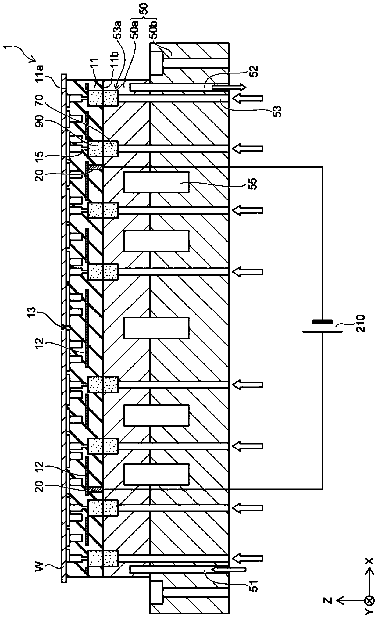
[0055] figure 1 It is a schematic cross-sectional view illustrating the electrostatic chuck 1 according to the present embodiment.

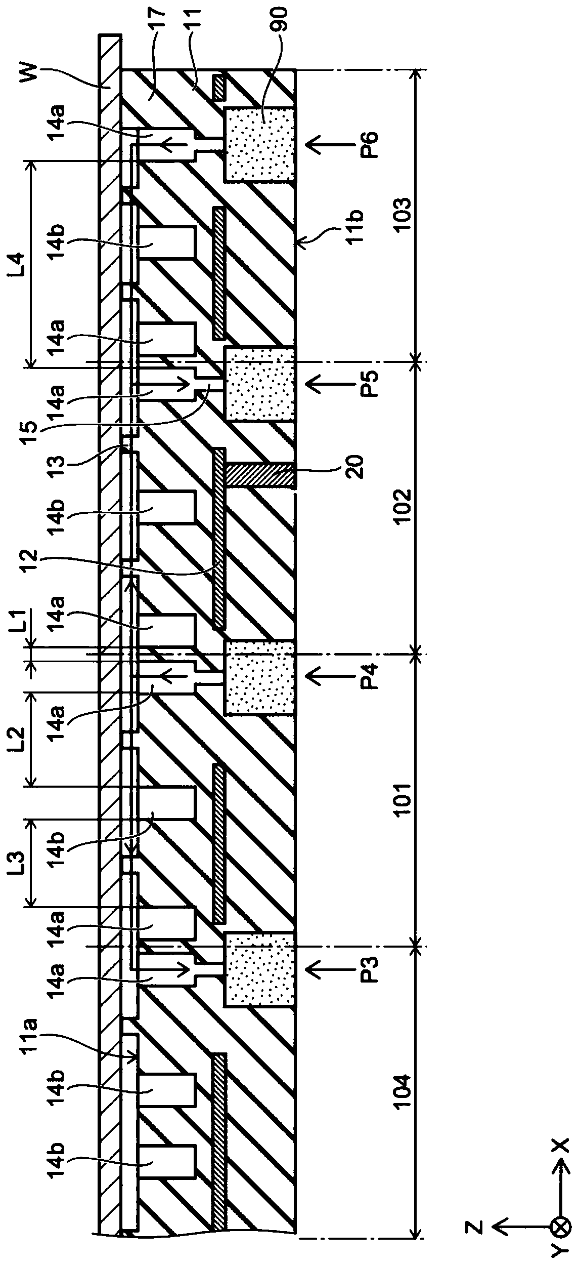
[0056] figure 2 It is a schematic cross-sectional view illustrating the ceramic electrolyte substrate 11 , the electrode 12 and the first porous porti...


PUM


Abstract

The invention provides an electrostatic chuck which particularly comprises the components of a base board; and a ceramic electrolyte substrate which has a first main surface. The electrostatic chuck is characterized in that the first main surface at least comprises a first area and a second area which is adjacent to the first area; the first area is provided with a plurality of first grooves, at least one first gas guiding hole which is connected with at least one of the plurality of first grooves, at least one second groove which extends in a direction that is crossed with the plurality of first grooves, wherein the planar shape of the plurality of first grooves is approximately circular, and the plurality of first grooves are coaxially arranged. The second groove is connected with at least two first grooves. When projected to a plane which is perpendicular with a first direction from the base board to the ceramic electrolyte substrate, at a part which is connected with the first grooves and the second groove, at least one part of the first gas guiding hole is superposed with at least one in the first grooves and the second groove.

Description

technical field [0001] An aspect of the present invention relates to an electrostatic chuck. Background technique [0002] The electrostatic chuck has, for example, a ceramic electrolyte substrate made of alumina or the like, and electrodes provided inside the ceramic electrolyte substrate. When electricity is applied externally to the electrodes, an electrostatic force is generated. An electrostatic chuck is a device that uses the generated electrostatic force to attract objects such as silicon wafers. In such an electrostatic chuck, an inert gas such as helium (He) (hereinafter simply referred to as gas) flows between the surface of the ceramic electrolyte substrate and the back surface of the object to control the temperature of the object. [0003] For example, in an apparatus that processes a substrate, such as a CVD (Chemical Vapor Deposition) apparatus, a sputtering apparatus, an ion implantation apparatus, and an etching apparatus, the temperature of the substrate ...

Claims


Application Information

Patent Timeline
Patent Type & Authority Applications(China)
IPC IPC(8): H01L21/683H01L21/67H01J37/32
CPCH01J37/32449H01J37/32715H01J37/32724H01J37/32862H01L21/67109H01L21/6833H01L21/6831
Inventor 池口雅文糸山哲朗西愿修一郎白石纯
Owner TOTO LTD
Why Eureka
Try Eureka