
Anti-blocking floor drain

An anti-clogging and floor drain technology, which is applied to waterway systems, climate change adaptation, drainage structures, etc., can solve problems such as floor drain blockage, achieve the effects of increasing service life, increasing use time, and speeding up cleaning

Active Publication Date: 2020-08-07
台州联豪自动化设备有限公司
View PDF6 Cites 6 Cited by
  • Summary
  • Abstract
  • Description
  • Claims
  • Application Information

AI Technical Summary

Problems solved by technology

[0004] The purpose of the present invention is to solve the disadvantages in the prior art that the floor drain is easily blocked by long hairs, and the floor drain needs to be cleaned frequently manually, and an anti-blocking floor drain is proposed.

Method used


Image

  • Anti-blocking floor drain
  • Anti-blocking floor drain
  • Anti-blocking floor drain

Examples


Embodiment 1

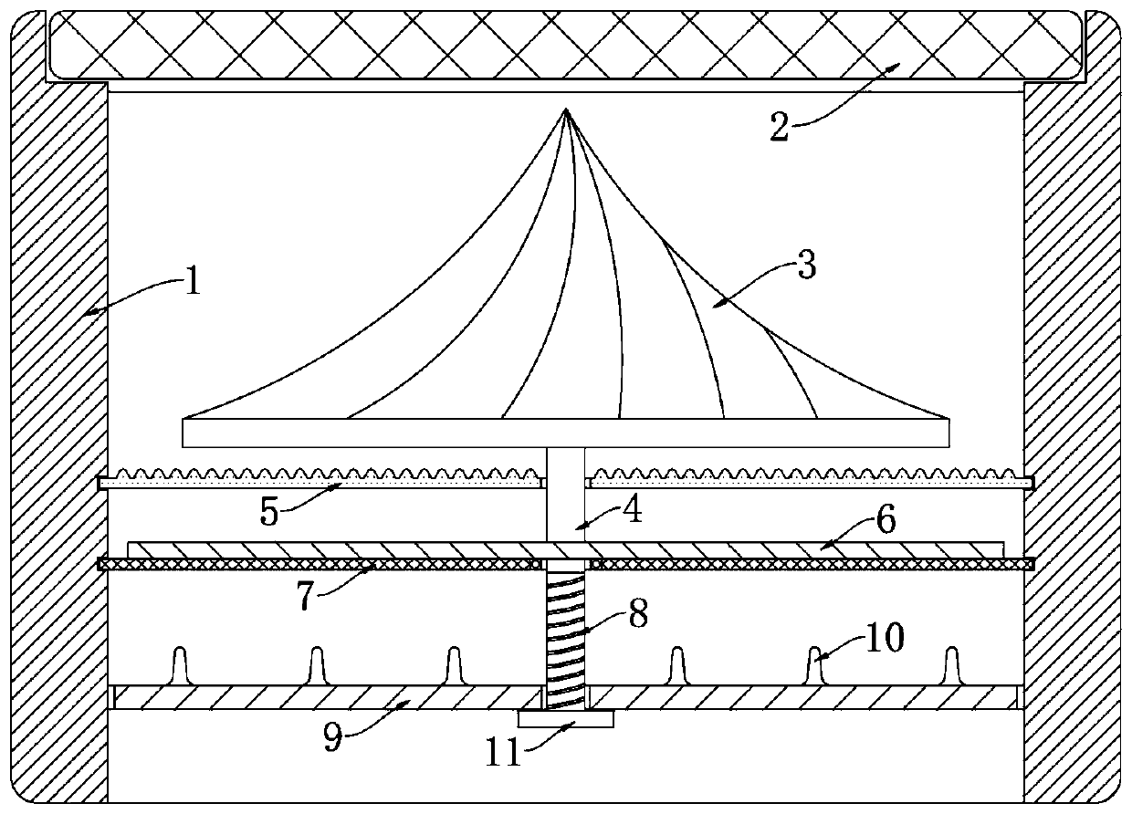
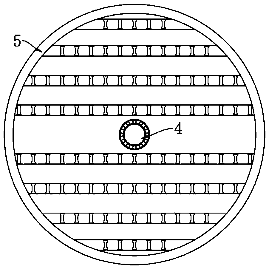
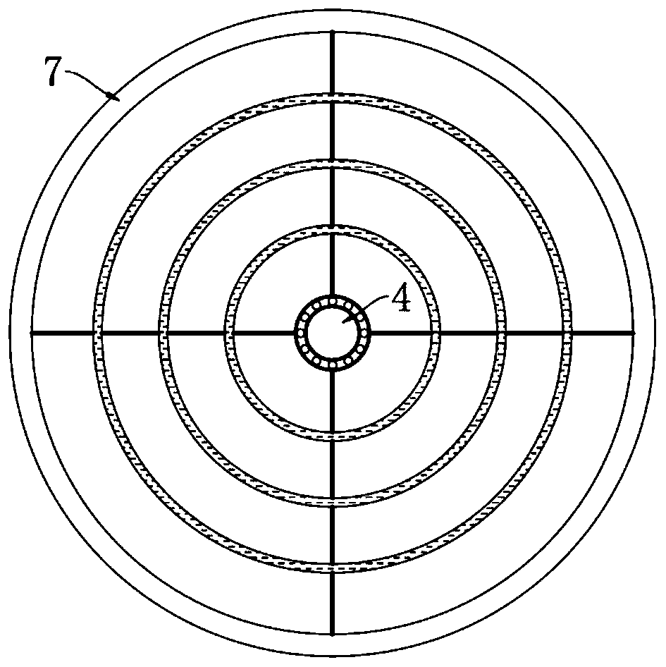
[0025] Reference Figure 1-4 , An anti-clogging floor drain, comprising a floor drain body 1 and a fine screen 2 placed on the upper end of the floor drain body 1. A sawing disc 5 and a coarse screen 7 are clamped in parallel from top to bottom in the floor drain body 1, and a sawing disc 5 A straight rod 4 is supported together with the coarse screen 7 through a bearing. The upper and lower ends of the straight rod 4 are respectively fixedly provided with a tapered block 3 and a limit plate 11, and the outer wall of the tapered block 3 is equidistantly circumferentially provided with oblique grooves. , When water flows through the tapered block 3, it will flow in the corresponding direction under the action of the chute. Under the force of the water flow, the tapered block 3 rotates, and the side wall of the straight rod 4 is provided with a thread groove 8 and the thread groove 8 Located below the coarse screen 7, the straight rod 4 is threadedly connected with a grid 9 throug...

Embodiment 2

[0034] Reference Figure 5-6 The difference between this embodiment and embodiment 1 is that: the outer side of the cone block 3 is wrapped with an antifouling layer, and a plurality of piezoelectric ceramics 19 are arranged between the antifouling layer and the cone block 3, and the antifouling layer can be coated The floor drain body 1 is made of rubber sheet covered with antifouling paint. A plurality of water storage tanks 13 are symmetrically opened in the side wall of the floor drain body 1, and a pressure block 14 is slidably installed in each water storage tank 13 through a conductive spring 12. A sealing ring is provided at the sliding joint of the inner wall of the sink 13, and the inner wall of the floor drain body 1 is provided with a plurality of water inlets 16 and a plurality of water nozzles 17, and each of the water inlets 16 and the water nozzles 17 are aligned with the position. The corresponding water storage tank 13 is connected, and each water inlet 16 is ...


PUM


Abstract

The invention discloses an anti-blocking floor drain. The anti-blocking floor drain comprises a floor drain body and a fine screen net placed at the upper end of the floor drain body, a saw cutting disc and a coarse screen net are parallelly arranged in the floor drain body in a clamped mode from top to bottom, the saw cutting disc and the coarse screen net are jointly supported with a straight rod through a bearing, a conical block and a limiting plate are correspondingly and fixedly arranged at the upper end and the lower end of the straight rod, chutes are equidistantly formed in the outerside wall of the conical block in a surrounded mode, a threaded groove is formed in the side wall of the straight rod, the threaded groove is located below the coarse screen net, the straight rod is connected with a mesh grid through the threaded groove in a threaded mode, the mesh grid is slidably connected with the inner side wall of the floor drain body in a sealed mode, top columns are uniformly distributed on the upper surface of the mesh grid, the straight rod is fixedly connected with a coil spring, and the coil spring is located between the saw cutting disc and the coarse screen net. According to the anti-blocking floor drain, the drainage speed of the floor drain can be increased, the long hair can further be prevented from blocking the floor drain, and the difficulty of cleaningthe hair in the floor drain is lowered.

Description

Technical field [0001] The invention relates to the technical field of drainage devices, in particular to an anti-clogging floor drain. Background technique [0002] The floor drain is an indispensable drainage appliance in the drainage system. The commonly used floor drain includes the water diversion pipe part and the filter part, and the filter part is mostly a combination of filters with different specifications. If the mesh of the filter is too large, it will not be able to For filtering function, if the mesh of the filter screen is too small, the ground drain is likely to be blocked, and people need to take out the filter screen and clean it manually. [0003] In bathrooms, hair salons and other places, in order to increase drainage, large-pore filters are often used, but when the user’s hair is long, the entangled hair is easy to block the floor drain and drainage pipes, so cleaners have to frequently check multiple places Cleaning the floor drain not only takes time and ef...

Claims


Application Information

Patent Timeline
Patent Type & Authority Applications(China)
IPC IPC(8): E03F5/04
CPCE03F5/0407Y02A30/60
Inventor 郭春燕吴军
Owner 台州联豪自动化设备有限公司
Learn More