Intelligent milling cutter for metal product

A metal product, intelligent technology, applied in milling cutters, metal processing equipment, manufacturing tools, etc., can solve problems such as troublesome, cumbersome operation steps, difficult disassembly and assembly of tools, etc., to improve stability, prolong service life, disassembly and assembly Simple and convenient process

Active Publication Date: 2020-08-07
深圳市创裕达电子有限公司
View PDF7 Cites 0 Cited by
  • Summary
  • Abstract
  • Description
  • Claims
  • Application Information

AI Technical Summary

Problems solved by technology

[0002] Milling cutter is a rotating tool with one or more cutter teeth used for milling. When working, each cutter tooth cuts off the allowance of the workpiece intermittently. Milling cutters are widely used in milling. Milling cutters are mainly used Used for machining planes, steps, grooves, forming surfaces and cutting off workpieces on milling machines. Existing milling cutters are usually composed of a cutter body and a blade fixed on the fixed part of the cutter body. After a period of use, the blade will become deformed due to wear It is too short to continue to use, and the tool needs to be replaced, but the existing tool is difficult to disassemble, and it is easy to cause unnecessary trouble during the processing process, and cannot meet the needs of modern industry.
[0003] The Chinese patent with the patent number CN201711257884.9 in the prior art discloses a milling cutter. The milling cutter can perform cutting operations through the tool, and achieve the purpose of connecting with the lathe through the connecting rod. Through the first clamping plate and the second clamping plate The mutual cooperation of the plates achieves the purpose of fixing the cutter on the connecting rod, making it misaligned with the first clamping plate, so that the cutter can be quickly disassembled, but there are still defects. In the process of disassembling the milling cutter, it is necessary to first Twist the screw rod and then pull the pull rod to complete the disassembly of the tool. The operation steps are cumbersome, which is not conducive to the quick disassembly and assembly of the milling cutter.

Method used


Image

  • Intelligent milling cutter for metal product
  • Intelligent milling cutter for metal product
  • Intelligent milling cutter for metal product

Examples


Embodiment 1

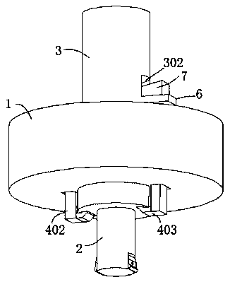
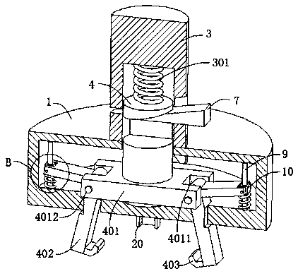
[0034] refer to figure 1 , figure 2 , image 3 , Figure 5 and Figure 6, an intelligent milling cutter for metal products, comprising a mount 1 and a cutter 2, the cutter 2 is connected to the bottom of the mount 1, the top of the mount 1 is connected to a connecting pipe 3, and the inner wall of the connecting pipe 3 is connected with a first elastic Element 301, the end of the first elastic element 301 away from the top inner wall of the connecting pipe 3 is connected with a moving rod 4, the moving rod 4 is movably connected in the mounting seat 1, the outer wall of the connecting pipe 3 is connected with a supporting plate 6, and the outer wall of the supporting plate 6 is slidingly connected with The first wedge block 7, the outer wall of the connecting pipe 3 is dug with the second concave hole 302 matched with the first wedge block 7, and the outer wall of the moving rod 4 is dug with a second groove 8 matched with the first wedge block 7. The outer wall of the ro...

Embodiment 2

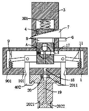
[0037] refer to figure 2 , image 3 , Figure 4 and Figure 8 , an intelligent milling cutter for metal products, which is basically the same as Embodiment 1, furthermore, the inner wall of the mounting seat 1 is connected with a guide rod 9, the outer wall of the guide rod 9 is slidably connected with a slider 10, and the outer wall of the guide rod 9 is covered Connected with a second elastic element 901, the second elastic element 901 is placed between the bottom wall of the slider 10 and the inner wall of the mounting base 1, the outer wall of the swing rod 402 is fixedly connected with a connecting rod 11, and the connecting rod 11 is far away from one end of the swing rod 402 A fourth groove 111 is excavated, and the inner wall of the fourth groove 111 is connected with a second rotating shaft 1111, and the slider 10 is connected to the inner wall of the fourth groove 111 through the rotation of the second rotating shaft 1111; Or in the process of moving down, the sw...

Embodiment 3

[0040] refer to figure 2 , image 3 and Figure 7 , an intelligent milling cutter for metal products, which is basically the same as that of Embodiment 1, furthermore, an oil cavity 14 and a first oil delivery pipeline 15 are excavated in the moving rod 4, and the oil cavity 14 and the first oil delivery pipeline 15 are connected to each other Connected, the bottom wall of the mounting base 1 is dug with an oil leakage hole 18, the oil leakage hole 18 is placed directly below the first oil delivery pipeline 15, a second oil delivery pipeline 19 is dug in the cutter 2, and the two ends of the second oil delivery pipeline 19 The square hole 2011 and the third groove 2021 communicate with each other respectively, the inner wall of the moving rod 4 is dug with a fifth groove 16, the inner wall of the fifth groove 16 is connected with a third elastic element 161, and the third elastic element 161 is far away from the fifth groove One end of the inner wall of 16 is connected with...


PUM


Abstract

The invention discloses an intelligent milling cutter for a metal product, and belongs to the technical field of machining cutting tools. The intelligent milling cutter for the metal product comprisesa mounting base and a cutting tool, the cutting tool is connected to the bottom of the mounting base, the top of the mounting base is connected with a connecting pipe, the inner wall of the connecting pipe is connected with a first elastic component, the end, away from the inner wall of the top of the connecting pipe, of the first elastic component is connected with a moving rod, the moving rod is movably connected into the mounting base, the outer wall of the connecting pipe is connected with a supporting plate, the outer wall of the supporting plate is slidably connected with a first wedgeblock, a second concave hole matched with the first wedge block is excavated in the outer wall of the connecting pipe, a second groove matched with the first wedge block is excavated in the outer wallof the moving rod, and the outer wall of the moving rod is fixedly connected with a connecting plate. Through moving of the first wedge block, the first wedge block and the moving rod are matched with each other to quickly mount and demount the cutting tool, the working efficiency is improved, and using demands of people are met.

Description

technical field [0001] The invention relates to the technical field of machining cutters, in particular to an intelligent milling cutter for metal products. Background technique [0002] Milling cutter is a rotating tool with one or more cutter teeth used for milling. When working, each cutter tooth cuts off the allowance of the workpiece intermittently. Milling cutters are widely used in milling. Milling cutters are mainly used Used for machining planes, steps, grooves, forming surfaces and cutting off workpieces on milling machines. Existing milling cutters are usually composed of a cutter body and a blade fixed on the fixed part of the cutter body. After a period of use, the blade will become deformed due to wear It is too short to continue to use, and the cutting tool needs to be replaced, but the existing cutting tool is difficult to disassemble and easily bring unnecessary troubles in the process of processing, and cannot meet the needs of modern industry. [0003] Th...

Claims


Application Information

Patent Timeline
IPC IPC(8): B23C5/00B23C5/28
CPCB23C5/00B23C5/28B23C2210/02
Inventor 袁海英
Owner 深圳市创裕达电子有限公司
Why Eureka
Try Eureka