Steel mill device

A technology of steel rolling and bottom plate, applied in workpiece cooling device, metal rolling, metal rolling and other directions, can solve the problems of low controllability of emulsion spraying area, poor strip processing effect, retention of metal particle residues, etc. To achieve the effect of being convenient for multiple use, convenient for filtering and storage, and good spraying effect

Pending Publication Date: 2020-08-07
李宁
View PDF0 Cites 2 Cited by
  • Summary
  • Abstract
  • Description
  • Claims
  • Application Information

AI Technical Summary

Problems solved by technology

[0004] 1. During the spraying process of the emulsion, the spraying angle of the general spraying head is fixed, and the spraying angle of the spraying head cannot be adjusted, which will cause the belt to be sprayed when the strip is located. The spraying angle of the steel has only one direction, and the emulsion is sprayed onto the steel belt and the rotating roller in the form of a water column, so that the controllability of the distribution of the emulsion spraying area is low, which will cause the spraying of the emulsion to be uneven. Uniformity, which makes the use of spraying less flexible, which in turn makes the use of the emulsion less effective, which makes the processing effect of the strip less effective;
[0005] 2. In the spraying of the emulsion, the emulsion is generally collected, but if the emulsion is collected and reused in this way, some solid metal residues in the emulsion will flow to the steel strip along with the emulsion , so that the metal particle residue stays on the steel strip, which affects the processing of the steel strip

Method used


Image

  • Steel mill device
  • Steel mill device
  • Steel mill device

Examples


Embodiment Construction

[0027] The technical solutions in the embodiments of the present invention will be clearly and completely described below in conjunction with the accompanying drawings in the embodiments of the present invention. Obviously, the described embodiments are only a part of the embodiments of the present invention, rather than all the embodiments. Based on the embodiments of the present invention, all other embodiments obtained by those of ordinary skill in the art without creative work shall fall within the protection scope of the present invention.

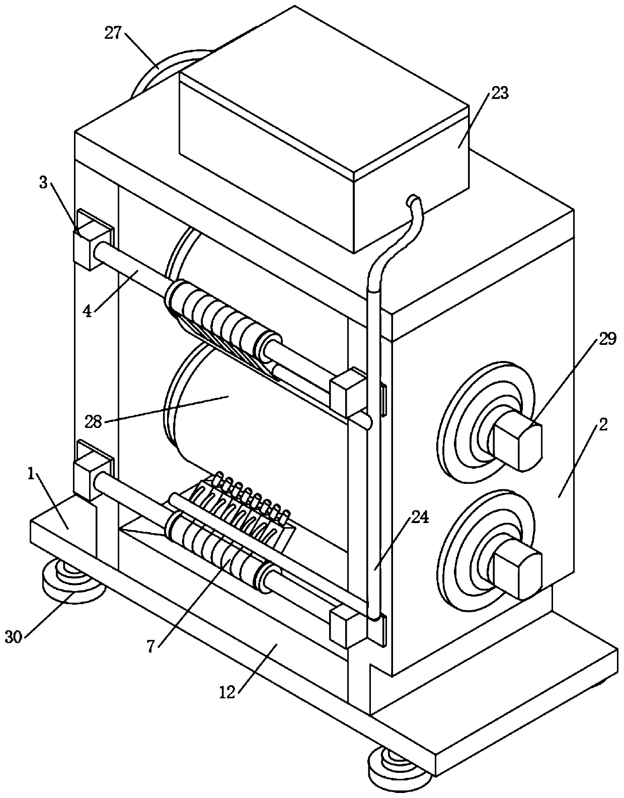
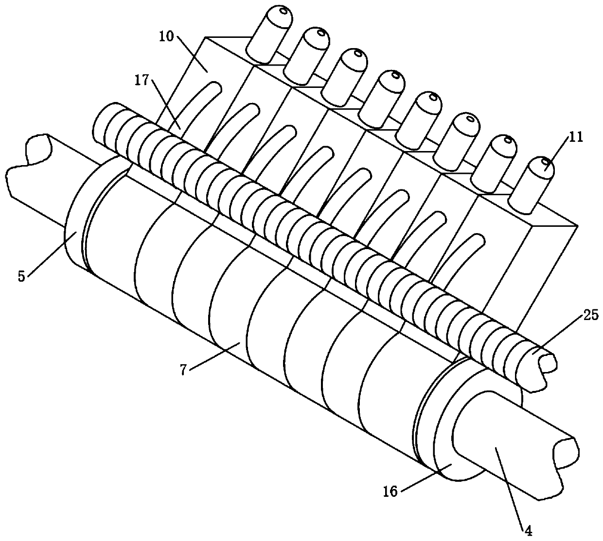
[0028] The present invention provides Figure 1-6 A steel rolling mill device shown includes a bottom plate 1. Both sides of the upper surface of the bottom plate 1 are fixedly connected with side plates 2. The top and bottom of the front of the two side plates 2 are fixedly connected with connecting pieces, and the connecting pieces are fixedly connected with The mounting block 3 and the mounting block 3 can facilitate the installation ...


PUM

PropertyMeasurementUnit
thicknessaaaaaaaaaa
widthaaaaaaaaaa

Abstract

The invention discloses a steel mill device. The device comprises a bottom plate, wherein side plates are fixedly connected to both sides of the upper surface of the bottom plate, a connecting rod isfixedly connected between two mounting blocks, one side of the outer wall of the connecting rod is fixedly connected with a first limiting ring in a sleeved mode, one side of the first limiting ring is fixedly connected with a fixing pipe, and the exterior of the fixing pipe is rotatably connected with at least three rotating pipes in a sleeve mode; and a fixing seat is connected with a spray head, the middle of the upper surface of the bottom plate is fixedly connected with a liquid collecting plate, the two sides of the liquid collecting plate are fixedly connected with the two side plates separately, a liquid collecting groove is formed in the middle of the liquid collecting plate, and a filter screen is fixedly connected to the bottom of the inner wall of a slag filtering out pipe in asleeve mode. According to the device, the arrangement mode that the rotating pipes are matched with the slag filtering out pipe is used, and the positions of the rotating pipes are thoroughly fixed through the first limiting ring and a second limiting ring so that the spraying angle of the spray head can be adjusted; and metal particles in an emulsion are filtered out through the filter screen, so that multiple utilization of the emulsion is facilitated, and resources are saved.

Description

Technical field [0001] The invention relates to the field of rolling mill devices, in particular to a steel rolling mill device. Background technique [0002] At present, cold-rolled steel strip refers to hot-rolled steel strip and steel plate as raw materials, which are rolled into strip steel and sheet by cold rolling mill at room temperature. The thickness is generally 0.1~3mm and the width is 100~2000mm. The plate has the advantages of good surface finish, good flatness, high dimensional accuracy and good mechanical properties. The cold-rolled strip steel needs to be processed by the cold-rolled strip mill during the production process. [0003] In the processing of steel strip by the steel rolling mill device, the cold-rolled strip rolling mill will use emulsion to spray the surface of the workpiece during processing. However, the following problems will occur when the emulsion sprays the workpiece: [0004] 1. In the spraying process of the emulsion, the spray angle of the ge...

Claims


Application Information

Patent Timeline
Patent Type & Authority Applications(China)
IPC IPC(8): B21B45/02B01D29/03
CPCB01D29/03B21B45/0233Y02P70/10
Inventor 李宁栾娟
Owner 李宁
Why Eureka
Try Eureka