
Permanent magnet brushless motor, robot joint, servo steering engine actuator and robot

A technology of permanent magnet brushless motors and permanent magnets, which is applied in servo servo actuators, permanent magnet brushless motors and robot joints, and in the field of robotics, and can solve limitations, low cogging torque, motor stability, and limited motor stator slots Full rate and other issues, to achieve the effect of increasing the slot full rate, increasing the motor constant and output power density, and meeting the design requirements

Pending Publication Date: 2020-08-04
SHANGHAI WUJI TECH CO LTD
View PDF0 Cites 6 Cited by
  • Summary
  • Abstract
  • Description
  • Claims
  • Application Information

AI Technical Summary

Problems solved by technology

[0003] The inventor found that there are at least the following problems in the related art: the existing motors for robots generally use stator teeth with boots to ensure low cogging torque and smooth operation of the motor
The stator teeth with boots limit the choice of winding process, so that the existing winding coils are usually directly wound on the stator teeth by a dedicated winding machine.
This processing method seriously limits the fullness of the stator slot of the motor
Existing robot motors generally use high-speed, low-torque motors designed with high reduction ratios to achieve high torque output, and there is still a big gap in improving actuator performance by increasing torque.

Method used


Image

  • Permanent magnet brushless motor, robot joint, servo steering engine actuator and robot
  • Permanent magnet brushless motor, robot joint, servo steering engine actuator and robot
  • Permanent magnet brushless motor, robot joint, servo steering engine actuator and robot

Examples


Embodiment Construction

[0044] The following will clearly and completely describe the technical solutions in the embodiments of the present invention with reference to the accompanying drawings in the embodiments of the present invention. Obviously, the described embodiments are only some, not all, embodiments of the present invention. Based on the embodiments of the present invention, all other embodiments obtained by persons of ordinary skill in the art without making creative efforts belong to the protection scope of the present invention.

[0045] In order to enable those skilled in the art to better understand the solution of the present invention, the present invention will be further described in detail below in conjunction with the accompanying drawings and specific embodiments.

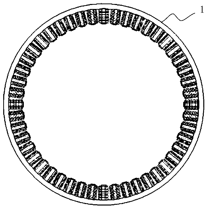
[0046] Such as Figure 1 to Figure 7 As shown, the embodiment of the present invention provides a permanent magnet brushless motor, which is a fractional slot inner rotor motor. The motor includes: a stator 1 and a...


PUM


Abstract

The invention relates to the technical field of motors and discloses a permanent magnet brushless motor, a robot joint, a servo steering engine actuator and a robot. The motor is a fractional slot inner rotor motor and comprises a stator and a rotor, the stator comprises a stator core and a stator winding. The stator winding is a centralized winding, and the stator core is of an integrated structure. The stator core comprises a stator yoke part and a stator tooth part. The stator tooth part comprises a plurality of stator teeth arranged on the stator yoke part, and an insulating layer is arranged on the surface of each stator tooth; the stator winding comprises a preset number of winding coils formed by machine winding, and each stator tooth is sleeved with x winding coils, wherein x is greater than or equal to 1; the rotor comprises a permanent magnet and a permanent magnet carrier; and the permanent magnet is used for excitation to generate a rotating magnetic field. According to theembodiment of the invention, the slot fullness rate can be improved and the electromagnetic design can be optimized under the condition of ensuring the operation stability of the motor, thereby improving the motor constant density and output power density of the motor.

Description

technical field [0001] The invention relates to the technical field of motors, in particular to a permanent magnet brushless motor, a robot joint, a servo servo actuator, and a robot. Background technique [0002] In recent years, the field of robotics has developed rapidly, especially special robots, such as legged robots. This type of robot puts forward high requirements for the actuator: low speed (below 500rpm), large torque, light weight, large output power, small size, and fast response. The performance of the actuator directly determines the performance of the robot, and the performance of the actuator is directly determined by the motor. The performance of the robot motor can be measured by the motor constant density, that is: the motor constant per unit mass, that is, the output torque / root (copper loss) / weight of the motor. For example, for a motor with an overall weight of about 200g, its motor constant per unit mass is generally less than The performance of m...

Claims


Application Information

Patent Timeline
IPC IPC(8): H02K1/14H02K3/18H02K1/27
CPCH02K1/146H02K3/18H02K1/274H02K3/522H02K2213/03B25J9/126H02K21/16H02K1/2783B25J17/00
Inventor 潘韫哲
Owner SHANGHAI WUJI TECH CO LTD
Learn More