
Non-contact mirror surface interval measurement method based on matrix optical calculation

A non-contact, optical computing technology, which is applied in the direction of optical instrument testing, measuring devices, testing optical performance, etc., can solve the problems of limiting the practicability of interval measuring instruments and unsatisfactory lens surface measurement, so as to realize the scope of equipment application and improve Effects on productivity and precision

Active Publication Date: 2020-08-04
CHANGCHUN JINGYI PHOTOELECTRIC TECH CO LTD
View PDF9 Cites 0 Cited by
  • Summary
  • Abstract
  • Description
  • Claims
  • Application Information

AI Technical Summary

Problems solved by technology

[0004] If there is no operation function of intelligent analysis, the selection of position parameters is made by the testers after repeated attempts, and finally determined based on experience. When the number of mirrors increases, it is difficult for testers to find suitable position parameters. It is possible to obtain all lens surfaces at one time and return Based on this empirical method, the maximum number of surfaces that can be measured at one time is about 8-10 pieces, which greatly limits the practicability of the interval measuring instrument
[0005] For example, the number of mirrors in the lithography machine system is mostly more than 10 pieces. Based on the empirically determined position parameter measurement scheme, multiple measurements are often required, and for some lens surfaces (such as glued surfaces), unsatisfactory results may occur. The intelligent analysis function of position parameters is particularly important

Method used


Image

  • Non-contact mirror surface interval measurement method based on matrix optical calculation
  • Non-contact mirror surface interval measurement method based on matrix optical calculation
  • Non-contact mirror surface interval measurement method based on matrix optical calculation

Examples


Embodiment Construction

[0050] The invention proposes a non-contact mirror interval measurement method based on matrix optical calculation, which can intelligently calculate mirror position parameters for any visible light optical system to be measured.

[0051] Taking a group of assembled standard lenses as an example, the standard lenses include 20 lens surfaces in total, and the specific implementation method based on the present invention is as follows.

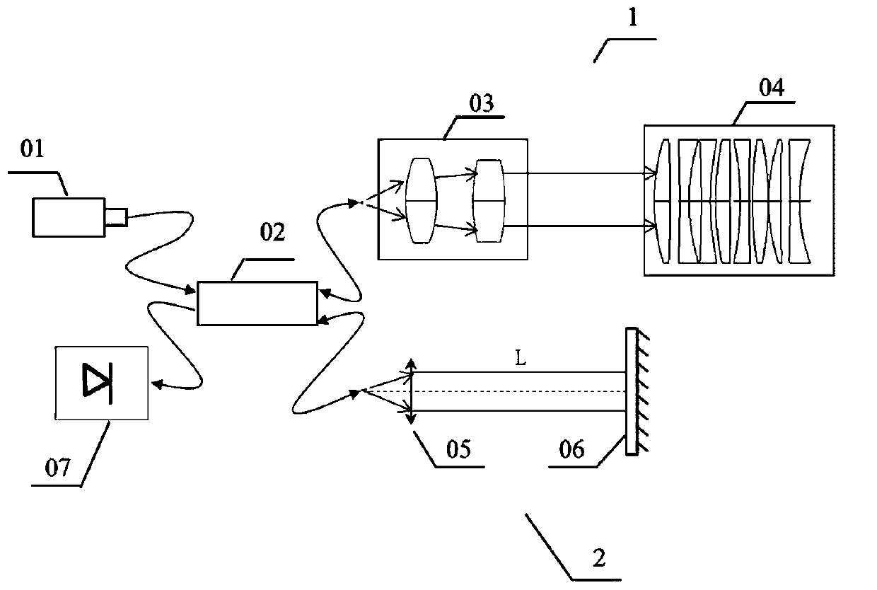
[0052] Such as figure 1 As shown, the measurement principle of the non-contact mirror distance measuring instrument is as follows: the light source adopts superluminescent light-emitting diode 01, and the light emitted by superluminescent light-emitting diode 01 is divided into two parts by fiber coupler 02, all the way into the measuring arm 1, and the light is sent by the measuring head 03 is collimated, and reflected by the surface of each lens in the measured mirror group 04, and then returns to the fiber coupler 02; all the way into the ref...


PUM


Abstract

The invention relates to a non-contact mirror surface interval measurement method based on matrix optical calculation. The method comprises the following steps: detecting interference signals of two paths of reflected light by using a detector; determining a position parameter candidate region in a light path of a measuring arm; and determining an optimal position parameter measured by a measuredlens group in the position parameter candidate region, and measuring thicknesses of all lenses in the measured lens group and air intervals of surfaces under the position parameter. Aiming at intervalmeasurement of a visible light optical system with any mirror surface number, an optimal lens interval and a working distance of a measuring head can be automatically and quickly found, energy maximization of all measured mirror surfaces can be balanced, and the working efficiency and precision of interval measurement are greatly improved.

Description

technical field [0001] The invention belongs to the technical field of optical adjustment and relates to a method for measuring the distance between mirrors used in a non-contact measuring instrument for distance between mirrors. Background technique [0002] As the last link of lens production, optical adjustment is one of the keys to ensure the performance of optical lenses by strictly controlling the center deviation and mirror spacing of optical lenses. In addition, the inspection and verification of the interval of the assembled optical lens group is also a problem often encountered by optical personnel. Based on the principle of low-coherence interference, the non-contact mirror interval measuring instrument can assist the installer to monitor and measure the interval in real time during the lens installation process, and can also accurately measure the interval of the finished optical mirror group. Compared with classical laser interferometers, low-coherence interfer...

Claims


Application Information

Patent Timeline
Patent Type & Authority Applications(China)
IPC IPC(8): G01M11/02
CPCG01M11/0221G01M11/0271
Inventor 罗晓霞孙金霞孙强赵建
Owner CHANGCHUN JINGYI PHOTOELECTRIC TECH CO LTD
Learn More